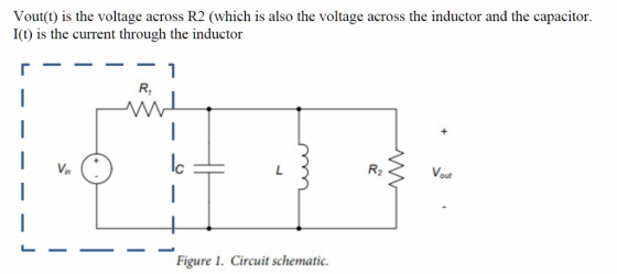


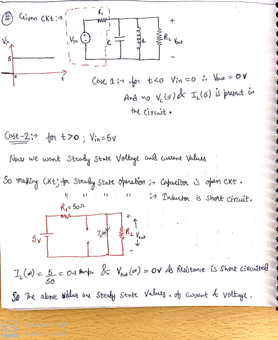
Find the Steady State Voltage and Current Values.
Develop the equation for i(t) , the current through the inductor and Vout(t).
I need help, I don't know if my calculations are correct, I found the neper frequency to be: a=439.109 rad/sec and resonant frequency to be Wo=14586.5 rad/sec.
This is a parallel step response RLC circuit
The circuit is underdamped.
Please show all work clearly so that I can understand the process.
Use this values for the above circuit, R1 50 ohms (the internal output impedance of the function generator), C47 uF, L 100 uH, R2-47 ohms.
For the circuit above, Vin is going to a step function voltage (0 for t0)
Homework Answers

Add Answer to:
Find the Steady State Voltage and Current Values. Develop the equation for i(t) , the current thr...
I need help to find the values! gures below (a-d), determine the values for R1, R2, voltage or type of op-amp based on the information listed. You may ors with an open circuit, short circuit, or v...
 I need help to find the values!
gures below (a-d), determine the values for R1, R2, voltage or type of op-amp based on the information listed. You may ors with an open circuit, short circuit, or values 1kn SRS1Mn. gain, voltage, a) 76 k2 Type: Non-Inverting Vout max R1 (based on Voutmas) 0.3V Type: Inverting, Av =-100 V/V Vin- b) R1 12V R1 12V Type: Buffer Vout- R1 =- c) +10 V R1 ーVout -10 V Type: Av- IV R2...
I need help to find the values!
gures below (a-d), determine the values for R1, R2, voltage or type of op-amp based on the information listed. You may ors with an open circuit, short circuit, or values 1kn SRS1Mn. gain, voltage, a) 76 k2 Type: Non-Inverting Vout max R1 (based on Voutmas) 0.3V Type: Inverting, Av =-100 V/V Vin- b) R1 12V R1 12V Type: Buffer Vout- R1 =- c) +10 V R1 ーVout -10 V Type: Av- IV R2...
1) An input step voltage Vin(t)=10 u(t) Volt is applied to the circuit shown below. The...
 1) An input step voltage Vin(t)=10 u(t) Volt is applied to the circuit shown below. The initial voltage on the capacitor is zero. Using Laplace transform techniques, calculate the resulting output voltage Vout(t). R1 R2 Vout 2000 Vin c1 1000 1uF R3 1000
2502 In the adjoining circuit schematic, in steady-state, the current flowing through the loop causes a...
 2502 In the adjoining circuit schematic, in steady-state, the current flowing through the loop causes a voltage drop across the resistor, having the waveform vr(t) = 15 cos (75 t) and a voltage drop across the capacitor given by ve(t) = 20 cos (75 t +90°) (a) Express the above two voltages in phasor form. (b) Find the source voltage shown in the circuit schematic, expressed in phasor form. (c) Express the source voltage v(t) as a function of time....
the voltage of the battery is 12V, and the values of the resistances are R1=5 ohms,...
 the voltage of the battery is 12V, and the values of
the resistances are R1=5 ohms, R2=10 ohms, R3= 15 ohms, and R4= 20
ohms.
Answer the following questions:
1. R1 and R3 are in :
2. R2 and R4 are in:
3 Compare the magnitude of the current through R2 and R3. which is
greater?
4. Compare the magnitude of the voltage across R1 and R3. which is
greater?
5. Compare the magnitude of the voltage across R2 and...
the voltage of the battery is 12V, and the values of
the resistances are R1=5 ohms, R2=10 ohms, R3= 15 ohms, and R4= 20
ohms.
Answer the following questions:
1. R1 and R3 are in :
2. R2 and R4 are in:
3 Compare the magnitude of the current through R2 and R3. which is
greater?
4. Compare the magnitude of the voltage across R1 and R3. which is
greater?
5. Compare the magnitude of the voltage across R2 and...
MA C2 Vin out R2 Component Values: R1 = 2k , R2 = 10㏀, Cl =...
 MA C2 Vin out R2 Component Values: R1 = 2k , R2 = 10㏀, Cl = C2 = 1nF Consider the filter circuit above. Assume that the operational amplifier is ideal (infinite gain and infinite input impedance) Problem 2: Derive the transfer function of the circuit, H(s) - Vout(s)Vin(s)
In the adjoining circuit schematic, in steady-state, the current flowing through the loop causes a voltage...
 In the adjoining circuit schematic, in steady-state, the current
flowing through the loop causes a voltage drop across the resistor,
having the waveform
vR(t) = 15 cos (75 t) and a voltage drop across the capacitor
given by vC(t) = 20 cos (75 t + 90⁰)
(a) Express the above two voltages in phasor form. (b) Find the
source voltage shown in the circuit schematic, expressed in phasor
form. (c) Express the source voltage v(t) as a function of
time....
In the adjoining circuit schematic, in steady-state, the current
flowing through the loop causes a voltage drop across the resistor,
having the waveform
vR(t) = 15 cos (75 t) and a voltage drop across the capacitor
given by vC(t) = 20 cos (75 t + 90⁰)
(a) Express the above two voltages in phasor form. (b) Find the
source voltage shown in the circuit schematic, expressed in phasor
form. (c) Express the source voltage v(t) as a function of
time....
2.5 kΩ 5H 3.0 uF The initial voltage at tO and current i(t)
 2.5 kΩ 5H 3.0 uF The initial voltage at t<0, V40)-100 v and current i(0)-0. At t=0 the switch is closed. a. (10 points) Find a differential equation (in time domain) for the voltage across the inductor. (10 points) The following expression is the solution for the differential equation find in part b. Determine all the parameters in the solution α, A, B and ω. b. V()e (A Cos(ot)+ BSin(r)) c. (2 points) Determine the steady state current and the...
For the next set of questions, consider the following circuit. The switch has been open for...
 For the next set of questions, consider the following circuit. The switch has been open for a long time. At t=0, it is closed. t=0 11 R1 3 1 3 C c IL R2 3 V = Assume the following values: 11=5mA 12=10mA R1=2K R2=2k L1=10mH C1 = luF Find the following: a) 11(0), the initial current through the inductor (in mA): b) The final current thru the inductor after the switch has been closed for a long time (in...
For the amplifier circuits in Figs.3 and 7: a. Write an expression for the output voltage,...
 For the amplifier circuits in Figs.3 and 7:
a. Write an expression for the output voltage, vo, in terms of
the resistor symbols and the input voltage, vin.
---For the first circuit (Fig. 3), the feedback resistor is the
series combination of R2 and R3. Use both of these resistor symbols
in your expression.
-- For circuit 2 (Fig. 7), assume that vin = 5V and ignore
potentiometer R1 and C3.
b. Using resistor values and input voltage amplitudes, calculate...
For the amplifier circuits in Figs.3 and 7:
a. Write an expression for the output voltage, vo, in terms of
the resistor symbols and the input voltage, vin.
---For the first circuit (Fig. 3), the feedback resistor is the
series combination of R2 and R3. Use both of these resistor symbols
in your expression.
-- For circuit 2 (Fig. 7), assume that vin = 5V and ignore
potentiometer R1 and C3.
b. Using resistor values and input voltage amplitudes, calculate...
 I need help to find the values!
gures below (a-d), determine the values for R1, R2, voltage or type of op-amp based on the information listed. You may ors with an open circuit, short circuit, or values 1kn SRS1Mn. gain, voltage, a) 76 k2 Type: Non-Inverting Vout max R1 (based on Voutmas) 0.3V Type: Inverting, Av =-100 V/V Vin- b) R1 12V R1 12V Type: Buffer Vout- R1 =- c) +10 V R1 ーVout -10 V Type: Av- IV R2...
I need help to find the values!
gures below (a-d), determine the values for R1, R2, voltage or type of op-amp based on the information listed. You may ors with an open circuit, short circuit, or values 1kn SRS1Mn. gain, voltage, a) 76 k2 Type: Non-Inverting Vout max R1 (based on Voutmas) 0.3V Type: Inverting, Av =-100 V/V Vin- b) R1 12V R1 12V Type: Buffer Vout- R1 =- c) +10 V R1 ーVout -10 V Type: Av- IV R2...
 1) An input step voltage Vin(t)=10 u(t) Volt is applied to the circuit shown below. The initial voltage on the capacitor is zero. Using Laplace transform techniques, calculate the resulting output voltage Vout(t). R1 R2 Vout 2000 Vin c1 1000 1uF R3 1000
 2502 In the adjoining circuit schematic, in steady-state, the current flowing through the loop causes a voltage drop across the resistor, having the waveform vr(t) = 15 cos (75 t) and a voltage drop across the capacitor given by ve(t) = 20 cos (75 t +90°) (a) Express the above two voltages in phasor form. (b) Find the source voltage shown in the circuit schematic, expressed in phasor form. (c) Express the source voltage v(t) as a function of time....
 the voltage of the battery is 12V, and the values of
the resistances are R1=5 ohms, R2=10 ohms, R3= 15 ohms, and R4= 20
ohms.
Answer the following questions:
1. R1 and R3 are in :
2. R2 and R4 are in:
3 Compare the magnitude of the current through R2 and R3. which is
greater?
4. Compare the magnitude of the voltage across R1 and R3. which is
greater?
5. Compare the magnitude of the voltage across R2 and...
the voltage of the battery is 12V, and the values of
the resistances are R1=5 ohms, R2=10 ohms, R3= 15 ohms, and R4= 20
ohms.
Answer the following questions:
1. R1 and R3 are in :
2. R2 and R4 are in:
3 Compare the magnitude of the current through R2 and R3. which is
greater?
4. Compare the magnitude of the voltage across R1 and R3. which is
greater?
5. Compare the magnitude of the voltage across R2 and...
 MA C2 Vin out R2 Component Values: R1 = 2k , R2 = 10㏀, Cl = C2 = 1nF Consider the filter circuit above. Assume that the operational amplifier is ideal (infinite gain and infinite input impedance) Problem 2: Derive the transfer function of the circuit, H(s) - Vout(s)Vin(s)
 In the adjoining circuit schematic, in steady-state, the current
flowing through the loop causes a voltage drop across the resistor,
having the waveform
vR(t) = 15 cos (75 t) and a voltage drop across the capacitor
given by vC(t) = 20 cos (75 t + 90⁰)
(a) Express the above two voltages in phasor form. (b) Find the
source voltage shown in the circuit schematic, expressed in phasor
form. (c) Express the source voltage v(t) as a function of
time....
In the adjoining circuit schematic, in steady-state, the current
flowing through the loop causes a voltage drop across the resistor,
having the waveform
vR(t) = 15 cos (75 t) and a voltage drop across the capacitor
given by vC(t) = 20 cos (75 t + 90⁰)
(a) Express the above two voltages in phasor form. (b) Find the
source voltage shown in the circuit schematic, expressed in phasor
form. (c) Express the source voltage v(t) as a function of
time....
 2.5 kΩ 5H 3.0 uF The initial voltage at t<0, V40)-100 v and current i(0)-0. At t=0 the switch is closed. a. (10 points) Find a differential equation (in time domain) for the voltage across the inductor. (10 points) The following expression is the solution for the differential equation find in part b. Determine all the parameters in the solution α, A, B and ω. b. V()e (A Cos(ot)+ BSin(r)) c. (2 points) Determine the steady state current and the...
 For the next set of questions, consider the following circuit. The switch has been open for a long time. At t=0, it is closed. t=0 11 R1 3 1 3 C c IL R2 3 V = Assume the following values: 11=5mA 12=10mA R1=2K R2=2k L1=10mH C1 = luF Find the following: a) 11(0), the initial current through the inductor (in mA): b) The final current thru the inductor after the switch has been closed for a long time (in...
 For the amplifier circuits in Figs.3 and 7:
a. Write an expression for the output voltage, vo, in terms of
the resistor symbols and the input voltage, vin.
---For the first circuit (Fig. 3), the feedback resistor is the
series combination of R2 and R3. Use both of these resistor symbols
in your expression.
-- For circuit 2 (Fig. 7), assume that vin = 5V and ignore
potentiometer R1 and C3.
b. Using resistor values and input voltage amplitudes, calculate...
For the amplifier circuits in Figs.3 and 7:
a. Write an expression for the output voltage, vo, in terms of
the resistor symbols and the input voltage, vin.
---For the first circuit (Fig. 3), the feedback resistor is the
series combination of R2 and R3. Use both of these resistor symbols
in your expression.
-- For circuit 2 (Fig. 7), assume that vin = 5V and ignore
potentiometer R1 and C3.
b. Using resistor values and input voltage amplitudes, calculate...
Most questions answered within 3 hours.
-
Where is the error in this code sequence?
String s1 = "Hello";
String s2 = "ello";...
asked 11 months ago -
Financial data for Joel de Paris, Inc., for last year
follow:
Joel de Paris, Inc.
Balance...
asked 11 months ago -
Consider this reaction:
Al2(SO4)3 (aq)+ BaCl3
(aq) Al2Cl6 (aq)- +
3BaSO4(s) . What is the...
asked 11 months ago -
Suppose that Savneet is considering increasing her
recent random sample from 20 car rentals to 40...
asked 11 months ago -
Trucks arrive at an unloading terminal at an average rate of 120
per hour.
Trucks arrive...
asked 11 months ago -
Why are methanol and ethanol completely soluble in water while
octanol is not very little soluble....
asked 11 months ago -
A facilities manager at a university reads in a research report
that the mean amount of...
asked 11 months ago -
When the CuSO4 is rehydrated by adding water to the anhydrous
compound, is this an endothermic...
asked 11 months ago -
A ray of sunlight is passing from diamond into crown glass; the
angle of incidence is...
asked 11 months ago -
A block of mass 0.249 kg is placed on top of a light, vertical
spring of...
asked 11 months ago -
how do the kidneys compensate in the presences of acidosis
a) trigger hyperventilate
b) reserve acid...
asked 11 months ago -
Question 501 pts
The rental rate of capital to the firm increases. Which of the
following...
asked 11 months ago