
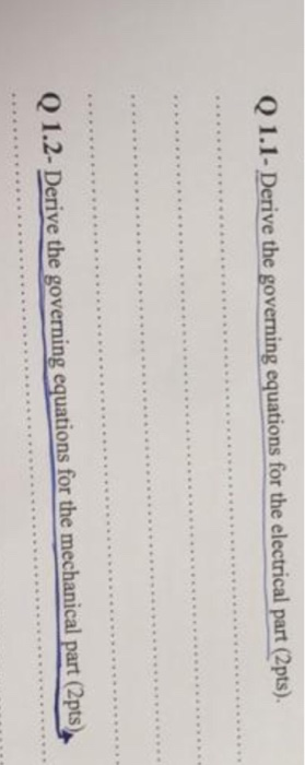
Q 1.1- Derive the governing equations for the electrical part (2pts). 1.2- Derive the governing equations for the mechanical part (2pts)
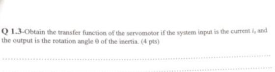
1.3-Obtain the transfer function of the servomotor if the system input is the current i, and the output is the rotation angle 0 of the inertia.(4 pts)
Homework Answers


Add Answer to:
Q 1- 08 Pts) Figure below is a diagram of a DC motor connected in parnllel to a current source i,...
01- (08 Pts) Figure below is a diagram of a DC motor connected in parallel to...
 01- (08 Pts) Figure below is a diagram of a DC motor connected in parallel to a current source is the torque and back-EMF constants of the motor are K. K respectively, the motor resistance is R, also modeled as connected in parallel, the motor inertia is I. (not shown), and the motor inductance is negligible. The motor load is an inertia compliance (stiffness) K and viscous friction coefficient b, and it is attached to the motor via a gear...
1. Consider a schematic diagram of the permanent magnet brushed DC motor used in Quanser system...
 1. Consider a schematic diagram of the permanent magnet brushed DC motor used in Quanser system with two inertia loads (Jh and J4) and no viscous damping as shown in Fig. 2-1.. Since there is no gear system, motor shaft angular position and velocity, 0m, and wm, respectively, are equal to disc load angular position and velocity 0, and w, respectively. Derive electrical and mechanical differential equations describing this DC motor dynamics, as well as the relationship between motor torque...
Electro-Mechanical Systems The electro-mechanical system shown below consists of an electric motor with input voltage V,...
 Electro-Mechanical Systems The electro-mechanical system shown below consists of an electric motor with input voltage V, which drive inertia I in the mechanical system (see torque T). Find the governing differential equations of motion for this electro-mechanical system in terms of the input voltage to the motor and output displacement y. Electrical System L > Vbac Voac Motor I - Motor Input Voltage Vpac - Motor Back EMF = Kas 0 0 - Motor Angular Velocity I - Motor Output...
u(t) ta(t) e(t) A DC motor is a electro-mechanical system, where mechanical motor is coupled with...
 u(t) ta(t) e(t) A DC motor is a electro-mechanical system, where mechanical motor is coupled with an electrical circuit. The motor shows up in the circuit equation as a voltage loss proportional to the motor speed, and the electrical system shows up as the input torque proportional to the armatura current DC motor equations are given by dw(t) dialt) where J is the mass moment of inertia in kg-m2, b is the damping coefficient in N-m-s, K is the motor...
Figure Q1(b) shows the simplified diagram of the armature controlled D.C. b) servomotors used in instruments...
 Figure Q1(b) shows the simplified diagram of the armature controlled D.C. b) servomotors used in instruments and employed a fixed permane nt magnet field. The control signal is app lied to the amature terminals. The inductance of armature winding is negligible. Obtain the transfer function of the servo mot or (assume K, K, and K, are constant) i) (10marks) Derive a state spa ce model for the servomotor (armature resistance is 0.2) (5marks) i) La Fixed field (if) Ra ww00...
(30 pts) A D.C. motor is shown below, where the inductance L and the resistance R model the armat...
 (30 pts) A D.C. motor is shown below, where the inductance L and the resistance R model the armature circuit. The voltage Vb represents the back-emf which is proportional to dθ/dt via K. The torque T generated by the motor is proportional to the i via a constant K. The inertia J represents the combined inertia of the motor and load. The viscous friction acting on the output shaft is B 1. pur voltaop a. A. (10 pts) Find the...
Consider the system given below. The output is y(displacement from equilibrium position) and the input is...
 Consider the system given below. The output is y(displacement from equilibrium position) and the input is V. (source voltage). The motor has an electrical constant Ke, a torque constant K, an armature inductance Lg and a resistance R. The rotor, shaft and disk together have inertia J and a viscous friction coefficient B. The disk has a radius ofr. (For the motor, assume that the torque is T = Ki,, and the back EMF is emf = KO). a. Derive...
i want to get part c,d The figure below is a gear-train mechanical system driven by...
 i want to get part c,d
The figure below is a gear-train mechanical system driven by a prescribed motion in the form of an angular displacement y(t). The motion is caused by an applied torque T(t) generated by a motor. The mass moment of inertias of the motor and the driving gear are J and J, respectively, whereas the mass moment of inertias of the load and the driven gear are J, and J2, respectively. The radii and angular displacements...
i want to get part c,d
The figure below is a gear-train mechanical system driven by a prescribed motion in the form of an angular displacement y(t). The motion is caused by an applied torque T(t) generated by a motor. The mass moment of inertias of the motor and the driving gear are J and J, respectively, whereas the mass moment of inertias of the load and the driven gear are J, and J2, respectively. The radii and angular displacements...
3.10 (Motor drive) Consider a system consisting of a motor driving two masses that are connected...
 3.10 (Motor drive) Consider a system consisting of a motor driving two masses that are connected by a torsional spring, as shown in the diagram below. Motor This system can represent a motor with a flexible shaft that drives a load. Assuming that the motor delivers a torque that is proportional to the current I, the dynamics of the system can be described by the equations dt dt (3.43) dtdt where Ф1 and P2 are the angles of the two...
D.C. motor is shown below, where the inductance L and the resistance R model the armature...
 D.C. motor is shown below, where the inductance
L and the resistance R model the
armature circuit. The voltage
Vbrepresents the back-emf
which is proportional to dθ/dt via
Kf. The torque T
generated by the motor is proportional to the
i via a constant
Kt. In this application, let the
constants Kt =
Kf. The inertia J
represents the combined inertia of the motor and load. The viscous
friction acting on the output shaft is b. Attached
to the shaft...
D.C. motor is shown below, where the inductance
L and the resistance R model the
armature circuit. The voltage
Vbrepresents the back-emf
which is proportional to dθ/dt via
Kf. The torque T
generated by the motor is proportional to the
i via a constant
Kt. In this application, let the
constants Kt =
Kf. The inertia J
represents the combined inertia of the motor and load. The viscous
friction acting on the output shaft is b. Attached
to the shaft...
 01- (08 Pts) Figure below is a diagram of a DC motor connected in parallel to a current source is the torque and back-EMF constants of the motor are K. K respectively, the motor resistance is R, also modeled as connected in parallel, the motor inertia is I. (not shown), and the motor inductance is negligible. The motor load is an inertia compliance (stiffness) K and viscous friction coefficient b, and it is attached to the motor via a gear...
 1. Consider a schematic diagram of the permanent magnet brushed DC motor used in Quanser system with two inertia loads (Jh and J4) and no viscous damping as shown in Fig. 2-1.. Since there is no gear system, motor shaft angular position and velocity, 0m, and wm, respectively, are equal to disc load angular position and velocity 0, and w, respectively. Derive electrical and mechanical differential equations describing this DC motor dynamics, as well as the relationship between motor torque...
 Electro-Mechanical Systems The electro-mechanical system shown below consists of an electric motor with input voltage V, which drive inertia I in the mechanical system (see torque T). Find the governing differential equations of motion for this electro-mechanical system in terms of the input voltage to the motor and output displacement y. Electrical System L > Vbac Voac Motor I - Motor Input Voltage Vpac - Motor Back EMF = Kas 0 0 - Motor Angular Velocity I - Motor Output...
 u(t) ta(t) e(t) A DC motor is a electro-mechanical system, where mechanical motor is coupled with an electrical circuit. The motor shows up in the circuit equation as a voltage loss proportional to the motor speed, and the electrical system shows up as the input torque proportional to the armatura current DC motor equations are given by dw(t) dialt) where J is the mass moment of inertia in kg-m2, b is the damping coefficient in N-m-s, K is the motor...
 Figure Q1(b) shows the simplified diagram of the armature controlled D.C. b) servomotors used in instruments and employed a fixed permane nt magnet field. The control signal is app lied to the amature terminals. The inductance of armature winding is negligible. Obtain the transfer function of the servo mot or (assume K, K, and K, are constant) i) (10marks) Derive a state spa ce model for the servomotor (armature resistance is 0.2) (5marks) i) La Fixed field (if) Ra ww00...
 (30 pts) A D.C. motor is shown below, where the inductance L and the resistance R model the armature circuit. The voltage Vb represents the back-emf which is proportional to dθ/dt via K. The torque T generated by the motor is proportional to the i via a constant K. The inertia J represents the combined inertia of the motor and load. The viscous friction acting on the output shaft is B 1. pur voltaop a. A. (10 pts) Find the...
 Consider the system given below. The output is y(displacement from equilibrium position) and the input is V. (source voltage). The motor has an electrical constant Ke, a torque constant K, an armature inductance Lg and a resistance R. The rotor, shaft and disk together have inertia J and a viscous friction coefficient B. The disk has a radius ofr. (For the motor, assume that the torque is T = Ki,, and the back EMF is emf = KO). a. Derive...
 i want to get part c,d
The figure below is a gear-train mechanical system driven by a prescribed motion in the form of an angular displacement y(t). The motion is caused by an applied torque T(t) generated by a motor. The mass moment of inertias of the motor and the driving gear are J and J, respectively, whereas the mass moment of inertias of the load and the driven gear are J, and J2, respectively. The radii and angular displacements...
i want to get part c,d
The figure below is a gear-train mechanical system driven by a prescribed motion in the form of an angular displacement y(t). The motion is caused by an applied torque T(t) generated by a motor. The mass moment of inertias of the motor and the driving gear are J and J, respectively, whereas the mass moment of inertias of the load and the driven gear are J, and J2, respectively. The radii and angular displacements...
 3.10 (Motor drive) Consider a system consisting of a motor driving two masses that are connected by a torsional spring, as shown in the diagram below. Motor This system can represent a motor with a flexible shaft that drives a load. Assuming that the motor delivers a torque that is proportional to the current I, the dynamics of the system can be described by the equations dt dt (3.43) dtdt where Ф1 and P2 are the angles of the two...
 D.C. motor is shown below, where the inductance
L and the resistance R model the
armature circuit. The voltage
Vbrepresents the back-emf
which is proportional to dθ/dt via
Kf. The torque T
generated by the motor is proportional to the
i via a constant
Kt. In this application, let the
constants Kt =
Kf. The inertia J
represents the combined inertia of the motor and load. The viscous
friction acting on the output shaft is b. Attached
to the shaft...
D.C. motor is shown below, where the inductance
L and the resistance R model the
armature circuit. The voltage
Vbrepresents the back-emf
which is proportional to dθ/dt via
Kf. The torque T
generated by the motor is proportional to the
i via a constant
Kt. In this application, let the
constants Kt =
Kf. The inertia J
represents the combined inertia of the motor and load. The viscous
friction acting on the output shaft is b. Attached
to the shaft...
Most questions answered within 3 hours.
-
Where is the error in this code sequence?
String s1 = "Hello";
String s2 = "ello";...
asked 11 months ago -
Financial data for Joel de Paris, Inc., for last year
follow:
Joel de Paris, Inc.
Balance...
asked 11 months ago -
Consider this reaction:
Al2(SO4)3 (aq)+ BaCl3
(aq) Al2Cl6 (aq)- +
3BaSO4(s) . What is the...
asked 11 months ago -
Suppose that Savneet is considering increasing her
recent random sample from 20 car rentals to 40...
asked 11 months ago -
Trucks arrive at an unloading terminal at an average rate of 120
per hour.
Trucks arrive...
asked 11 months ago -
Why are methanol and ethanol completely soluble in water while
octanol is not very little soluble....
asked 11 months ago -
A facilities manager at a university reads in a research report
that the mean amount of...
asked 11 months ago -
When the CuSO4 is rehydrated by adding water to the anhydrous
compound, is this an endothermic...
asked 11 months ago -
A ray of sunlight is passing from diamond into crown glass; the
angle of incidence is...
asked 11 months ago -
A block of mass 0.249 kg is placed on top of a light, vertical
spring of...
asked 11 months ago -
how do the kidneys compensate in the presences of acidosis
a) trigger hyperventilate
b) reserve acid...
asked 11 months ago -
Question 501 pts
The rental rate of capital to the firm increases. Which of the
following...
asked 11 months ago