
Homework Answers
Add Answer to:
The following problem must be completed, in entirety, in order for this HW to be graded. If this ...
MEC 432 Mechanical Design I and draw the MDE theory please The bearings at A and...
 MEC
432
Mechanical Design I
and draw the MDE theory please
The bearings at A and B exert only y and a components of force on the shaft. If Sy = 150 MPa for the selected ductile material, determine the factor of safety if the shaft diameter is 40 mm. Use the maximum distortion-energy theory of failure. Show the following procedures through the calculation steps (Free Body diagram (FBD), Reaction at A and D, Bending moment diagram, point of max....
MEC
432
Mechanical Design I
and draw the MDE theory please
The bearings at A and B exert only y and a components of force on the shaft. If Sy = 150 MPa for the selected ductile material, determine the factor of safety if the shaft diameter is 40 mm. Use the maximum distortion-energy theory of failure. Show the following procedures through the calculation steps (Free Body diagram (FBD), Reaction at A and D, Bending moment diagram, point of max....
The correct answers are provided as following by the professor, please refrain from answering if the...
 The correct answers are provided as following by the
professor, please refrain from answering if the correct answers are
not provided
provide detailed answer showing your work step by
step,
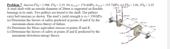
Problem 7 Ans:(a) FSH= 1.966, FS=2.19 (b) om-H= 174.4MPa, o-K= A steel shaft with an outside diameter of 20mm is supported on flexible bearings at its ends. Two pulleys are keyed to the shaft. The pulleys carry belt tensions as shown. The steel's yield strength is oy= 350MPa. (a) Determine...
The correct answers are provided as following by the
professor, please refrain from answering if the correct answers are
not provided
provide detailed answer showing your work step by
step,
Problem 7 Ans:(a) FSH= 1.966, FS=2.19 (b) om-H= 174.4MPa, o-K= A steel shaft with an outside diameter of 20mm is supported on flexible bearings at its ends. Two pulleys are keyed to the shaft. The pulleys carry belt tensions as shown. The steel's yield strength is oy= 350MPa. (a) Determine...
a. create the FBD, shear, Moment, and torque diagrams for the shaft. B. what is the...
 a. create the FBD, shear,
Moment, and torque diagrams for the shaft.
B. what is the location of maximum stress (plane of interest for
the design)? you may disregard all feometric stress concentration
factors.
C.what stresses are in existence on the plane of interest? Do
not calculate them, what is exists.
d. Draw the wave forms for the stresses in existence on the
plane of interest.
e. you must determine if this shaft will have an infinite life,
what failure...
a. create the FBD, shear,
Moment, and torque diagrams for the shaft.
B. what is the location of maximum stress (plane of interest for
the design)? you may disregard all feometric stress concentration
factors.
C.what stresses are in existence on the plane of interest? Do
not calculate them, what is exists.
d. Draw the wave forms for the stresses in existence on the
plane of interest.
e. you must determine if this shaft will have an infinite life,
what failure...
5-36 This problem illustrates that the factor of safety for a machine element depends on the...
 5-36 This problem illustrates that the factor of safety for a machine element depends on the particular point selected for analysis. Here you are to compute factors of safety, based upon the distortion- energy theory, for stress elements at A and B of the member shown in the figure. This bar is made of AISI 1006 cold-drawn steel and is loaded by the forces F = 0.55 kN, P = 4.0 kN, and T = 25 N·m. -100 mm- Problem...
do fast Question 2 20 marks e rotating solid steel shaf is simply supported by bearings at poithe force F by a disc...
 do fast
Question 2 20 marks e rotating solid steel shaf is simply supported by bearings at poithe force F by a disc (not shown) which meshes with the dise at disc acts vertically as shown in figure where F = 2 kN. The shan A of T 400 Nm. The shaft is machined from steel. a. Using a factor of safety of 3, shaft dia the distortion energy theory and modified-Goodman. bearing shoulders for b. Draw a free hand...
do fast
Question 2 20 marks e rotating solid steel shaf is simply supported by bearings at poithe force F by a disc (not shown) which meshes with the dise at disc acts vertically as shown in figure where F = 2 kN. The shan A of T 400 Nm. The shaft is machined from steel. a. Using a factor of safety of 3, shaft dia the distortion energy theory and modified-Goodman. bearing shoulders for b. Draw a free hand...
The figure shows a transmission shaft. The steel solid shaft is 200 mm long between self-aligning...
 The figure shows a transmission shaft. The steel solid shaft is 200 mm long between self-aligning bearings at A and B. Belt forces in the same horizontal direction) are applied to a 120-mm diameter sheave at C. The left end of the shaft is connected to an electric motor attached to a clutch by means of a flexible coupling. Nothing is attached to the right end (it is free). Assuming the shaft has a constant diameter, d. (a) Perform the...
Question 1 Time Allowed: 2 hours The figure shows a transmission shaft. The steel solid shaft...
 Question 1 Time Allowed: 2 hours The figure shows a transmission shaft. The steel solid shaft is 200 mm long between self-aligning bearings at A and B. Belt forces (in the same horizontal direction) are applied to a 120-mm diameter sheave at C. The left end of the shaft is connected to an electric motor attached to a clutch by means of a flexible coupling. Nothing is attach to the right end (it is free). Assuming the shaft has a...
The figure above shows a shaft mounted in bearings A and D and having pulleys at B and C.
 The figure above shows a shaft mounted in bearings A and D and having pulleys at B and C. The shaft is 20 mm in diameter and made of AISI 1020 CD steel. The forces shown acting on the pulley surfaces represent the belt tensions. The shaft is concerned with yielding and fatigue failure. [Stress analysis) (1) Draw the free body diagrams and find reaction forces at A and D in the xy and xz planes. (2) Draw the shear force and moment...
4. Here is a similar problem with pulleys and shafts, complicated slightly due to the fact...
 4. Here is a similar problem with pulleys and shafts, complicated slightly due to the fact that there are forces in two planes, not just one, as previously. Dimensions in the figure are in mm. Some additional dimensions are: dahaft 18 mm 200 mm300 mm 300 400 Ts Te 150 d Assume bearings 0 and C are frictionless. Assume tensile forces are T = 200 N and Ti 40 N. Further assume steady-state operation. (a) On pulley A, suppose the...
The rotating solid steel shaft is simply supported by bearings at points B and C and is driven by a disc (not shown) which meshes with the disc at D as shown.
 The rotating solid steel shaft is simply supported by bearings at points B and C and is driven by a disc (not shown) which meshes with the disc at D as shown. The force F from the drive disc acts vertically as shown in figure where F = 2.2 kN. The shaft transmits a torque to point A of TA=380 Nm. The shaft is machined from steel. a. Using a factor of safety of 3, determine the shaft diameter at various...
 MEC
432
Mechanical Design I
and draw the MDE theory please
The bearings at A and B exert only y and a components of force on the shaft. If Sy = 150 MPa for the selected ductile material, determine the factor of safety if the shaft diameter is 40 mm. Use the maximum distortion-energy theory of failure. Show the following procedures through the calculation steps (Free Body diagram (FBD), Reaction at A and D, Bending moment diagram, point of max....
MEC
432
Mechanical Design I
and draw the MDE theory please
The bearings at A and B exert only y and a components of force on the shaft. If Sy = 150 MPa for the selected ductile material, determine the factor of safety if the shaft diameter is 40 mm. Use the maximum distortion-energy theory of failure. Show the following procedures through the calculation steps (Free Body diagram (FBD), Reaction at A and D, Bending moment diagram, point of max....
 The correct answers are provided as following by the
professor, please refrain from answering if the correct answers are
not provided
provide detailed answer showing your work step by
step,
Problem 7 Ans:(a) FSH= 1.966, FS=2.19 (b) om-H= 174.4MPa, o-K= A steel shaft with an outside diameter of 20mm is supported on flexible bearings at its ends. Two pulleys are keyed to the shaft. The pulleys carry belt tensions as shown. The steel's yield strength is oy= 350MPa. (a) Determine...
The correct answers are provided as following by the
professor, please refrain from answering if the correct answers are
not provided
provide detailed answer showing your work step by
step,
Problem 7 Ans:(a) FSH= 1.966, FS=2.19 (b) om-H= 174.4MPa, o-K= A steel shaft with an outside diameter of 20mm is supported on flexible bearings at its ends. Two pulleys are keyed to the shaft. The pulleys carry belt tensions as shown. The steel's yield strength is oy= 350MPa. (a) Determine...
 a. create the FBD, shear,
Moment, and torque diagrams for the shaft.
B. what is the location of maximum stress (plane of interest for
the design)? you may disregard all feometric stress concentration
factors.
C.what stresses are in existence on the plane of interest? Do
not calculate them, what is exists.
d. Draw the wave forms for the stresses in existence on the
plane of interest.
e. you must determine if this shaft will have an infinite life,
what failure...
a. create the FBD, shear,
Moment, and torque diagrams for the shaft.
B. what is the location of maximum stress (plane of interest for
the design)? you may disregard all feometric stress concentration
factors.
C.what stresses are in existence on the plane of interest? Do
not calculate them, what is exists.
d. Draw the wave forms for the stresses in existence on the
plane of interest.
e. you must determine if this shaft will have an infinite life,
what failure...
 5-36 This problem illustrates that the factor of safety for a machine element depends on the particular point selected for analysis. Here you are to compute factors of safety, based upon the distortion- energy theory, for stress elements at A and B of the member shown in the figure. This bar is made of AISI 1006 cold-drawn steel and is loaded by the forces F = 0.55 kN, P = 4.0 kN, and T = 25 N·m. -100 mm- Problem...
 do fast
Question 2 20 marks e rotating solid steel shaf is simply supported by bearings at poithe force F by a disc (not shown) which meshes with the dise at disc acts vertically as shown in figure where F = 2 kN. The shan A of T 400 Nm. The shaft is machined from steel. a. Using a factor of safety of 3, shaft dia the distortion energy theory and modified-Goodman. bearing shoulders for b. Draw a free hand...
do fast
Question 2 20 marks e rotating solid steel shaf is simply supported by bearings at poithe force F by a disc (not shown) which meshes with the dise at disc acts vertically as shown in figure where F = 2 kN. The shan A of T 400 Nm. The shaft is machined from steel. a. Using a factor of safety of 3, shaft dia the distortion energy theory and modified-Goodman. bearing shoulders for b. Draw a free hand...
 The figure shows a transmission shaft. The steel solid shaft is 200 mm long between self-aligning bearings at A and B. Belt forces in the same horizontal direction) are applied to a 120-mm diameter sheave at C. The left end of the shaft is connected to an electric motor attached to a clutch by means of a flexible coupling. Nothing is attached to the right end (it is free). Assuming the shaft has a constant diameter, d. (a) Perform the...
 Question 1 Time Allowed: 2 hours The figure shows a transmission shaft. The steel solid shaft is 200 mm long between self-aligning bearings at A and B. Belt forces (in the same horizontal direction) are applied to a 120-mm diameter sheave at C. The left end of the shaft is connected to an electric motor attached to a clutch by means of a flexible coupling. Nothing is attach to the right end (it is free). Assuming the shaft has a...
 4. Here is a similar problem with pulleys and shafts, complicated slightly due to the fact that there are forces in two planes, not just one, as previously. Dimensions in the figure are in mm. Some additional dimensions are: dahaft 18 mm 200 mm300 mm 300 400 Ts Te 150 d Assume bearings 0 and C are frictionless. Assume tensile forces are T = 200 N and Ti 40 N. Further assume steady-state operation. (a) On pulley A, suppose the...
Most questions answered within 3 hours.
-
Where is the error in this code sequence?
String s1 = "Hello";
String s2 = "ello";...
asked 11 months ago -
Financial data for Joel de Paris, Inc., for last year
follow:
Joel de Paris, Inc.
Balance...
asked 11 months ago -
Consider this reaction:
Al2(SO4)3 (aq)+ BaCl3
(aq) Al2Cl6 (aq)- +
3BaSO4(s) . What is the...
asked 11 months ago -
Suppose that Savneet is considering increasing her
recent random sample from 20 car rentals to 40...
asked 11 months ago -
Trucks arrive at an unloading terminal at an average rate of 120
per hour.
Trucks arrive...
asked 11 months ago -
Why are methanol and ethanol completely soluble in water while
octanol is not very little soluble....
asked 11 months ago -
A facilities manager at a university reads in a research report
that the mean amount of...
asked 11 months ago -
When the CuSO4 is rehydrated by adding water to the anhydrous
compound, is this an endothermic...
asked 11 months ago -
A ray of sunlight is passing from diamond into crown glass; the
angle of incidence is...
asked 11 months ago -
A block of mass 0.249 kg is placed on top of a light, vertical
spring of...
asked 11 months ago -
how do the kidneys compensate in the presences of acidosis
a) trigger hyperventilate
b) reserve acid...
asked 11 months ago -
Question 501 pts
The rental rate of capital to the firm increases. Which of the
following...
asked 11 months ago