
Homework Answers
Add Answer to:
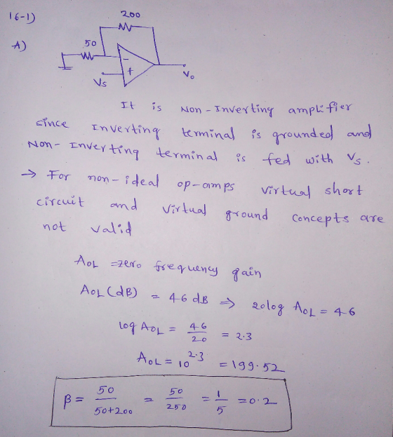
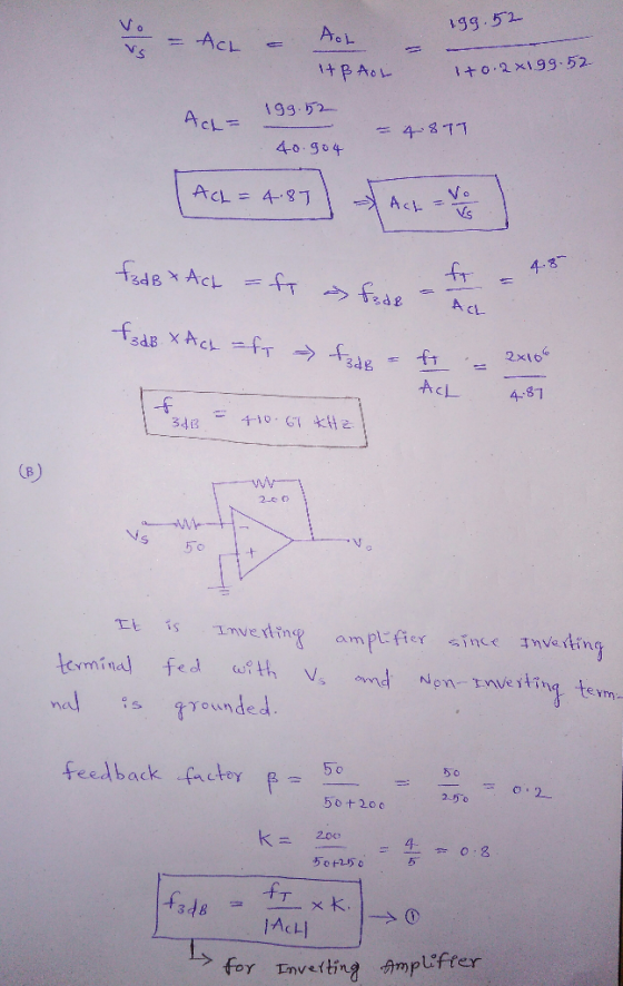
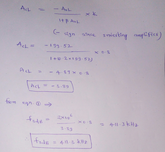
16-1. Assume non-ideal ideal opamps with zero frequency gain 46dB and unity-gain frequency fr 2MH...
12. The open-loop voltage gain ("A') of an ideal operational amplifier is 1. infinite 2. unity...
 12. The open-loop voltage gain ("A') of an ideal operational amplifier is 1. infinite 2. unity 3. zero 4. inverting 5. non-invertinsg 2 13. If(Vii-Vo)-0 then the output of an ideal operational amplifier is 1. inverting 2. unity 3. infinite 4. zero 5. non-inverting 2
a The operational amplifier in Figure 3.a has a slew rate of 0.5V/us and a unity gain bandwid of 5 MHz. Determine () the voltage gain, and (ii) the maximum input frequency such that the output wa...
 a The operational amplifier in Figure 3.a has a slew rate of 0.5V/us and a unity gain bandwid of 5 MHz. Determine () the voltage gain, and (ii) the maximum input frequency such that the output waveform is undistorted. with Vpeak 1V and frequency f. () Determine the cutoff frequency, (ii) plot, to scale, the you use this integrator if the input frequency is 30 KHz? Explain your answer. that any feedback resistance is fixed to 5k2. b. In the...
Practice [25%] The circuit shown left below is a waveform generation circuit, which consists of an integrator and a bistable multi-vibrator. The triangle symbol represents a unity-gain inverting...
 Practice [25%] The circuit shown left below is a waveform generation circuit, which consists of an integrator and a bistable multi-vibrator. The triangle symbol represents a unity-gain inverting amplifier such that V1 -v3 . R1-3k1, R2-2kQ, R3-1 ka, and C 0.1μF. The opamps are ideal except that they saturate at +10V and-10V. Be careful that the opamp in the bistable multi-vibrator is configured in a positive feedback way (a) On your answer book, sketch the output (v2) versus the input...
Q3. Consider a single loop unity feedback control system of the open loop transfer function (a) Find the range of values of the gain K and the parameter p so that: (i) The overshoot is less than 10%....
 Q3. Consider a single loop unity feedback control system of the open loop transfer function (a) Find the range of values of the gain K and the parameter p so that: (i) The overshoot is less than 10%. (ii)The settling time is less than 4 seconds Note: , 4.6 M. = exp CO 40% (b)What are the three elements in a PID controller? Considering each in turn, explain the main ways in which varying the parameters affects the closed-loop system...
b) The Nyquist plot of a unity feedback control system is as shown in Figure Q5(b)....
 b) The Nyquist plot of a unity feedback control system is as shown in Figure Q5(b). Nyqulst Diagram x 10 1.5 1- System: N Real: -9.08e-005 0.5- Imag: -5.62e-006 Frequency (rad/sec): -104 -0.5 -15 -1.5 0.5 0.5 1.5 1 2.5 3.5 Real Axis x 10 Figure Q5(b) K If the transfer function of the system is given as G(s) (s+10)(s+50)(s+150) determine the following: The closed loop stability of the system using Nyquist Stability Criterion. i) ii) Gain margin and phase...
1) (10 pts) Consider the unity feedback system shown in the figure: For each of the...
 1) (10 pts) Consider the unity feedback system shown in the figure: For each of the following transfer function G(s), plot its Bode plots using Matlab command "bode", and then work on the plots to find out the crossover frequency phase margin . the phase crossover frequency and the gain margin GM: (a) G(s)= , the S+4 s(s + l)(s + 2)(s +10) (b) Gs)100
ONLY NEED HELP WITH C AND D PLEASE! The differentiator circuit shown in Figure 1 uses an op-amp with ideal characteristics C1 Figure 1 (a) Prove that the gain of the circuit is given by the following...
 ONLY NEED HELP WITH C AND D PLEASE!
The differentiator circuit shown in Figure 1 uses an op-amp with ideal characteristics C1 Figure 1 (a) Prove that the gain of the circuit is given by the following expression using first principles for an ideal op-amp (2 marks) Gain = - (1 + juli R 1) (b) If the differentiator frequency (at unity gain) is 100Hz and the high frequency gain is 40dB and R2 is 220kQ, design the rest of...
ONLY NEED HELP WITH C AND D PLEASE!
The differentiator circuit shown in Figure 1 uses an op-amp with ideal characteristics C1 Figure 1 (a) Prove that the gain of the circuit is given by the following expression using first principles for an ideal op-amp (2 marks) Gain = - (1 + juli R 1) (b) If the differentiator frequency (at unity gain) is 100Hz and the high frequency gain is 40dB and R2 is 220kQ, design the rest of...
The Bode plots for a plant, G(s), used in a unity feedback system are shown in Figure P10.7. Do the following: Find the gain margin, phase margin, zero dB frequency, 180° frequency, and the closed-l...
 The Bode plots for a plant, G(s), used in a unity feedback
system are shown in Figure P10.7. Do the following:
Find the gain margin, phase margin, zero dB frequency, 180°
frequency, and the closed-loop bandwidth.
Use your results in Part a to estimate the damping ratio,
percent overshoot, settling time, and peak time.
ANSWERS GIVEN BY PROFESSOR
1. Gain margin = 20dB, Phase margin = 55 deg, Zero dB frequency
= 1rad/s, 180deg frequency = 4.5rad/s, bandwidth (-7dB) closed-loop...
The Bode plots for a plant, G(s), used in a unity feedback
system are shown in Figure P10.7. Do the following:
Find the gain margin, phase margin, zero dB frequency, 180°
frequency, and the closed-loop bandwidth.
Use your results in Part a to estimate the damping ratio,
percent overshoot, settling time, and peak time.
ANSWERS GIVEN BY PROFESSOR
1. Gain margin = 20dB, Phase margin = 55 deg, Zero dB frequency
= 1rad/s, 180deg frequency = 4.5rad/s, bandwidth (-7dB) closed-loop...
i. Prove that the voltage gain of following configuration is unity (1) if: Vcc = 16...
 i. Prove that the voltage gain of following configuration is unity (1) if: Vcc = 16 V R3 = 330 ko RE= 2.2 ko ro= 50 ko B= 80 Vcc RB C2 HE EO RE Z Based on the above configuration, find the value of voltage and current gain and compare the voltage gain with question (1) if: Vcc = 12 V R3 = 390 kO RE= 5.6 k 2 7 = 40 k2 B= 120
a=8 Q.17,3,3,3, 2, 1, 1] Consider the unity feedback system: 10 (5) (Where "a" is the...
 a=8
Q.17,3,3,3, 2, 1, 1] Consider the unity feedback system: 10 (5) (Where "a" is the right most integer of your UQUID. If Ss(s+a) | this is zero, use the next non-zero integer. For example, if your UQUID is 437056780, then "a" should be 8). Do the following four parts (a, b, c and d) by calculation only i.e. without making Bode plot. a. Find the phase cross-over frequency, gain margin, gain cross-over frequency (this will not be easy!) and...
a=8
Q.17,3,3,3, 2, 1, 1] Consider the unity feedback system: 10 (5) (Where "a" is the right most integer of your UQUID. If Ss(s+a) | this is zero, use the next non-zero integer. For example, if your UQUID is 437056780, then "a" should be 8). Do the following four parts (a, b, c and d) by calculation only i.e. without making Bode plot. a. Find the phase cross-over frequency, gain margin, gain cross-over frequency (this will not be easy!) and...
 12. The open-loop voltage gain ("A') of an ideal operational amplifier is 1. infinite 2. unity 3. zero 4. inverting 5. non-invertinsg 2 13. If(Vii-Vo)-0 then the output of an ideal operational amplifier is 1. inverting 2. unity 3. infinite 4. zero 5. non-inverting 2
 a The operational amplifier in Figure 3.a has a slew rate of 0.5V/us and a unity gain bandwid of 5 MHz. Determine () the voltage gain, and (ii) the maximum input frequency such that the output waveform is undistorted. with Vpeak 1V and frequency f. () Determine the cutoff frequency, (ii) plot, to scale, the you use this integrator if the input frequency is 30 KHz? Explain your answer. that any feedback resistance is fixed to 5k2. b. In the...
 Practice [25%] The circuit shown left below is a waveform generation circuit, which consists of an integrator and a bistable multi-vibrator. The triangle symbol represents a unity-gain inverting amplifier such that V1 -v3 . R1-3k1, R2-2kQ, R3-1 ka, and C 0.1μF. The opamps are ideal except that they saturate at +10V and-10V. Be careful that the opamp in the bistable multi-vibrator is configured in a positive feedback way (a) On your answer book, sketch the output (v2) versus the input...
 Q3. Consider a single loop unity feedback control system of the open loop transfer function (a) Find the range of values of the gain K and the parameter p so that: (i) The overshoot is less than 10%. (ii)The settling time is less than 4 seconds Note: , 4.6 M. = exp CO 40% (b)What are the three elements in a PID controller? Considering each in turn, explain the main ways in which varying the parameters affects the closed-loop system...
 b) The Nyquist plot of a unity feedback control system is as shown in Figure Q5(b). Nyqulst Diagram x 10 1.5 1- System: N Real: -9.08e-005 0.5- Imag: -5.62e-006 Frequency (rad/sec): -104 -0.5 -15 -1.5 0.5 0.5 1.5 1 2.5 3.5 Real Axis x 10 Figure Q5(b) K If the transfer function of the system is given as G(s) (s+10)(s+50)(s+150) determine the following: The closed loop stability of the system using Nyquist Stability Criterion. i) ii) Gain margin and phase...
 1) (10 pts) Consider the unity feedback system shown in the figure: For each of the following transfer function G(s), plot its Bode plots using Matlab command "bode", and then work on the plots to find out the crossover frequency phase margin . the phase crossover frequency and the gain margin GM: (a) G(s)= , the S+4 s(s + l)(s + 2)(s +10) (b) Gs)100
 ONLY NEED HELP WITH C AND D PLEASE!
The differentiator circuit shown in Figure 1 uses an op-amp with ideal characteristics C1 Figure 1 (a) Prove that the gain of the circuit is given by the following expression using first principles for an ideal op-amp (2 marks) Gain = - (1 + juli R 1) (b) If the differentiator frequency (at unity gain) is 100Hz and the high frequency gain is 40dB and R2 is 220kQ, design the rest of...
ONLY NEED HELP WITH C AND D PLEASE!
The differentiator circuit shown in Figure 1 uses an op-amp with ideal characteristics C1 Figure 1 (a) Prove that the gain of the circuit is given by the following expression using first principles for an ideal op-amp (2 marks) Gain = - (1 + juli R 1) (b) If the differentiator frequency (at unity gain) is 100Hz and the high frequency gain is 40dB and R2 is 220kQ, design the rest of...
 The Bode plots for a plant, G(s), used in a unity feedback
system are shown in Figure P10.7. Do the following:
Find the gain margin, phase margin, zero dB frequency, 180°
frequency, and the closed-loop bandwidth.
Use your results in Part a to estimate the damping ratio,
percent overshoot, settling time, and peak time.
ANSWERS GIVEN BY PROFESSOR
1. Gain margin = 20dB, Phase margin = 55 deg, Zero dB frequency
= 1rad/s, 180deg frequency = 4.5rad/s, bandwidth (-7dB) closed-loop...
The Bode plots for a plant, G(s), used in a unity feedback
system are shown in Figure P10.7. Do the following:
Find the gain margin, phase margin, zero dB frequency, 180°
frequency, and the closed-loop bandwidth.
Use your results in Part a to estimate the damping ratio,
percent overshoot, settling time, and peak time.
ANSWERS GIVEN BY PROFESSOR
1. Gain margin = 20dB, Phase margin = 55 deg, Zero dB frequency
= 1rad/s, 180deg frequency = 4.5rad/s, bandwidth (-7dB) closed-loop...
 i. Prove that the voltage gain of following configuration is unity (1) if: Vcc = 16 V R3 = 330 ko RE= 2.2 ko ro= 50 ko B= 80 Vcc RB C2 HE EO RE Z Based on the above configuration, find the value of voltage and current gain and compare the voltage gain with question (1) if: Vcc = 12 V R3 = 390 kO RE= 5.6 k 2 7 = 40 k2 B= 120
 a=8
Q.17,3,3,3, 2, 1, 1] Consider the unity feedback system: 10 (5) (Where "a" is the right most integer of your UQUID. If Ss(s+a) | this is zero, use the next non-zero integer. For example, if your UQUID is 437056780, then "a" should be 8). Do the following four parts (a, b, c and d) by calculation only i.e. without making Bode plot. a. Find the phase cross-over frequency, gain margin, gain cross-over frequency (this will not be easy!) and...
a=8
Q.17,3,3,3, 2, 1, 1] Consider the unity feedback system: 10 (5) (Where "a" is the right most integer of your UQUID. If Ss(s+a) | this is zero, use the next non-zero integer. For example, if your UQUID is 437056780, then "a" should be 8). Do the following four parts (a, b, c and d) by calculation only i.e. without making Bode plot. a. Find the phase cross-over frequency, gain margin, gain cross-over frequency (this will not be easy!) and...
Most questions answered within 3 hours.
-
Where is the error in this code sequence?
String s1 = "Hello";
String s2 = "ello";...
asked 11 months ago -
Financial data for Joel de Paris, Inc., for last year
follow:
Joel de Paris, Inc.
Balance...
asked 11 months ago -
Consider this reaction:
Al2(SO4)3 (aq)+ BaCl3
(aq) Al2Cl6 (aq)- +
3BaSO4(s) . What is the...
asked 11 months ago -
Suppose that Savneet is considering increasing her
recent random sample from 20 car rentals to 40...
asked 11 months ago -
Trucks arrive at an unloading terminal at an average rate of 120
per hour.
Trucks arrive...
asked 11 months ago -
Why are methanol and ethanol completely soluble in water while
octanol is not very little soluble....
asked 11 months ago -
A facilities manager at a university reads in a research report
that the mean amount of...
asked 11 months ago -
When the CuSO4 is rehydrated by adding water to the anhydrous
compound, is this an endothermic...
asked 11 months ago -
A ray of sunlight is passing from diamond into crown glass; the
angle of incidence is...
asked 11 months ago -
A block of mass 0.249 kg is placed on top of a light, vertical
spring of...
asked 11 months ago -
how do the kidneys compensate in the presences of acidosis
a) trigger hyperventilate
b) reserve acid...
asked 11 months ago -
Question 501 pts
The rental rate of capital to the firm increases. Which of the
following...
asked 11 months ago