

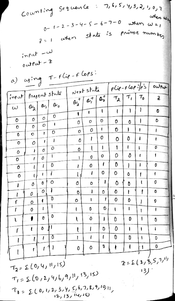
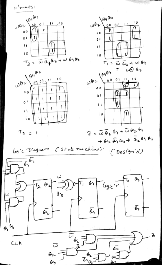
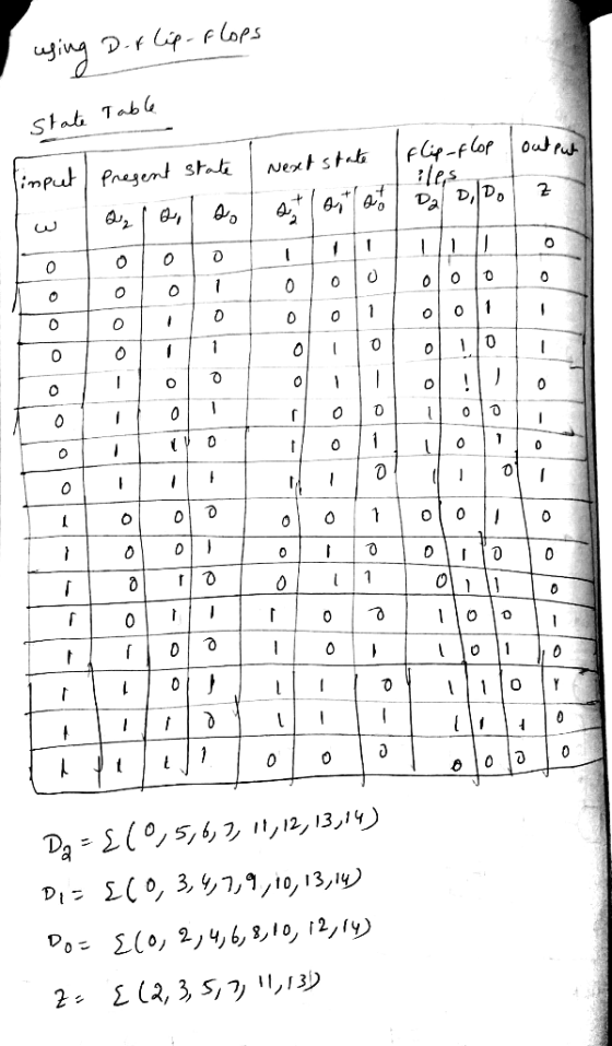
4. Design A: use T flip-flops to design the counter and derive the expression for flip-flop inputs and output z find the total cost. (10pts) 5. Design B: use D flip-flops to design the counter and derive the expression for flip-flop inputs and z. find the total cost. (10pts for group of 2 students only) 6. Compare between the two designs in number 4 & 5 and choose the best design to be implemented. Justify your choice with technical reasons. (Spts for group of 2 students only)
Homework Answers


Add Answer to:
Design a 3-bit counter that has only one input, w. It counts down 7, 6,5,... 0, 7,.. whenever w-0...
Design a 3-bit down counter FSM with no inputs and three outputs. Do this using a...
Design a 3-bit down counter FSM with no inputs and three outputs. Do this using a T flip flop. a. Draw a state diagram and the corresponding state table. b. Derive the equations for output functions and flip-flop input functions c. Draw the logic circuit diagram
a. Design a count up/count down counter that counts from 0 up to 4, then 4 down to 0 using D flip flop.
2. Synchronous Counters: a. Design a count up/count down counter that counts from 0 up to 4, then 4 down to 0 using D flip flop. b. Design a count up counter that counts from 0 up to 12 using JK flip flops.
Design a two-bit up/down binary counter using D flip-flops that can count in binary from 0 to 7.
Design a two-bit up/down binary counter using D flip-flops that can count in binary from 0 to 7. When the control input x is 0, the circuit counts down, and when it is 1, the circuit counts up. (a) Obtain the state table of the two-bit counter. (b) Obtain the state diagram (c) Draw the logic diagram of the circuit.
14. Design a cyclic counter that produces the binary sequence 0, 2, 3,1. o..if the control signal...
 14?
14. Design a cyclic counter that produces the binary sequence 0, 2, 3,1. o..if the control signal X is 0 but produces the binary sequence 0, 1,3,2.0, if the control signal X is1.Use D flip-flops. (a) Draw the state diagram; (6 points (b) Draw the input, present state-next state, excitation table: (6 points) (c) Derive the minimal SOP expressions for the D inputs of the flip-flops using K-maps. Draw the logic circuit realization of the counter, using only NAND...
14?
14. Design a cyclic counter that produces the binary sequence 0, 2, 3,1. o..if the control signal X is 0 but produces the binary sequence 0, 1,3,2.0, if the control signal X is1.Use D flip-flops. (a) Draw the state diagram; (6 points (b) Draw the input, present state-next state, excitation table: (6 points) (c) Derive the minimal SOP expressions for the D inputs of the flip-flops using K-maps. Draw the logic circuit realization of the counter, using only NAND...
Design a BCD counter with four T flip-flops. - The state table should have the present...
Design a BCD counter with four T flip-flops. - The state table should have the present state, next state, output, minterm, and flip-flop inputs. The output signal Y = 0 only during the counter transition from 1001 to 0000, otherwise, Y = 1 (for each valid input). - The input equation for TQ4, TQ2 and TQ1 in SOP. - The equation of the output signal Y in SOP.
Design an up/down counter with four states (0, 1, 2, 3) using clocked J-K flip-flops. A...
 Design an up/down counter with four states (0, 1, 2, 3) using clocked J-K flip-flops. A control signal x is used as follows: When x 0 the machine counts forward (up), when x , backward (down). Simulate using MultiSim and attach a simulation printout X Please address the following in your report 1. State Table 2. State Diagram 3. Flip-Flop Excitation Tables 4 K-Map Simplification and resulting diagram 5. Multisim Simulation 6. Conclusion/Discussion 7. References
Design an up/down counter with...
Design an up/down counter with four states (0, 1, 2, 3) using clocked J-K flip-flops. A control signal x is used as follows: When x 0 the machine counts forward (up), when x , backward (down). Simulate using MultiSim and attach a simulation printout X Please address the following in your report 1. State Table 2. State Diagram 3. Flip-Flop Excitation Tables 4 K-Map Simplification and resulting diagram 5. Multisim Simulation 6. Conclusion/Discussion 7. References
Design an up/down counter with...
1) Design a synchronous 3-bit binary UP/DOWN counter uses the following counting pattern 10.2.3.7.6.40.1.3...) the counter...
 1) Design a synchronous 3-bit binary UP/DOWN counter uses the following counting pattern 10.2.3.7.6.40.1.3...) the counter will count in this pattern indefinitely when the input X is equal to 1. When the input the counter will reverse direction and count in the opposite pattern 0. 4 7310) Complete the state diagram, transition table, New state s and solve for the recitation equations for flipflops that will perform this function. (You do not need to draw the flip-flops Use the state...
the design for a 3-bit synchronous down counter built with T flip- ive-high input H; when...
 the design for a 3-bit synchronous down counter built with T flip- ive-high input H; when H is high the count holds, points) Draw flops. Include a synchronous, act otherwise the circuit counts down. T Q T Q T Q
Question 3 40 pts Design a counter that starts at "0" and increases by two until...
 Question 3 40 pts Design a counter that starts at "0" and increases by two until you reach "6" and then starts at "0" again and continues counting in the same way. Your digital circuit design must be implemented using D-flipflops, and your answer must include: . . The transition graph (be detailed and contain all shoper directions and values) The next state truth table (needs to include the present and next-state) The K-map(s) for next-state equation Determine the optimal...
6. Design a 2-bit binary counter that counts, 0, 1, 2, 3, 0,. Use the 74LS374 IC, which has eight D flip-flops on it. They are positive-edge triggered, but it will not matter at all here You may draw...
 6. Design a 2-bit binary counter that counts, 0, 1, 2, 3, 0,. Use the 74LS374 IC, which has eight D flip-flops on it. They are positive-edge triggered, but it will not matter at all here You may draw a state diagram and then fill in the table Present State Q(t) Next State (D(t) - Q(t+1)) Q1(t) Qo(t) 7. Design a BCD binary counter that counts from 0 to 9 then back to 0 and repeat, displaying the count on...
 14?
14. Design a cyclic counter that produces the binary sequence 0, 2, 3,1. o..if the control signal X is 0 but produces the binary sequence 0, 1,3,2.0, if the control signal X is1.Use D flip-flops. (a) Draw the state diagram; (6 points (b) Draw the input, present state-next state, excitation table: (6 points) (c) Derive the minimal SOP expressions for the D inputs of the flip-flops using K-maps. Draw the logic circuit realization of the counter, using only NAND...
14?
14. Design a cyclic counter that produces the binary sequence 0, 2, 3,1. o..if the control signal X is 0 but produces the binary sequence 0, 1,3,2.0, if the control signal X is1.Use D flip-flops. (a) Draw the state diagram; (6 points (b) Draw the input, present state-next state, excitation table: (6 points) (c) Derive the minimal SOP expressions for the D inputs of the flip-flops using K-maps. Draw the logic circuit realization of the counter, using only NAND...
 Design an up/down counter with four states (0, 1, 2, 3) using clocked J-K flip-flops. A control signal x is used as follows: When x 0 the machine counts forward (up), when x , backward (down). Simulate using MultiSim and attach a simulation printout X Please address the following in your report 1. State Table 2. State Diagram 3. Flip-Flop Excitation Tables 4 K-Map Simplification and resulting diagram 5. Multisim Simulation 6. Conclusion/Discussion 7. References
Design an up/down counter with...
Design an up/down counter with four states (0, 1, 2, 3) using clocked J-K flip-flops. A control signal x is used as follows: When x 0 the machine counts forward (up), when x , backward (down). Simulate using MultiSim and attach a simulation printout X Please address the following in your report 1. State Table 2. State Diagram 3. Flip-Flop Excitation Tables 4 K-Map Simplification and resulting diagram 5. Multisim Simulation 6. Conclusion/Discussion 7. References
Design an up/down counter with...
 1) Design a synchronous 3-bit binary UP/DOWN counter uses the following counting pattern 10.2.3.7.6.40.1.3...) the counter will count in this pattern indefinitely when the input X is equal to 1. When the input the counter will reverse direction and count in the opposite pattern 0. 4 7310) Complete the state diagram, transition table, New state s and solve for the recitation equations for flipflops that will perform this function. (You do not need to draw the flip-flops Use the state...
 the design for a 3-bit synchronous down counter built with T flip- ive-high input H; when H is high the count holds, points) Draw flops. Include a synchronous, act otherwise the circuit counts down. T Q T Q T Q
 Question 3 40 pts Design a counter that starts at "0" and increases by two until you reach "6" and then starts at "0" again and continues counting in the same way. Your digital circuit design must be implemented using D-flipflops, and your answer must include: . . The transition graph (be detailed and contain all shoper directions and values) The next state truth table (needs to include the present and next-state) The K-map(s) for next-state equation Determine the optimal...
 6. Design a 2-bit binary counter that counts, 0, 1, 2, 3, 0,. Use the 74LS374 IC, which has eight D flip-flops on it. They are positive-edge triggered, but it will not matter at all here You may draw a state diagram and then fill in the table Present State Q(t) Next State (D(t) - Q(t+1)) Q1(t) Qo(t) 7. Design a BCD binary counter that counts from 0 to 9 then back to 0 and repeat, displaying the count on...
Most questions answered within 3 hours.
-
Where is the error in this code sequence?
String s1 = "Hello";
String s2 = "ello";...
asked 11 months ago -
Financial data for Joel de Paris, Inc., for last year
follow:
Joel de Paris, Inc.
Balance...
asked 11 months ago -
Consider this reaction:
Al2(SO4)3 (aq)+ BaCl3
(aq) Al2Cl6 (aq)- +
3BaSO4(s) . What is the...
asked 11 months ago -
Suppose that Savneet is considering increasing her
recent random sample from 20 car rentals to 40...
asked 11 months ago -
Trucks arrive at an unloading terminal at an average rate of 120
per hour.
Trucks arrive...
asked 11 months ago -
Why are methanol and ethanol completely soluble in water while
octanol is not very little soluble....
asked 11 months ago -
A facilities manager at a university reads in a research report
that the mean amount of...
asked 11 months ago -
When the CuSO4 is rehydrated by adding water to the anhydrous
compound, is this an endothermic...
asked 11 months ago -
A ray of sunlight is passing from diamond into crown glass; the
angle of incidence is...
asked 11 months ago -
A block of mass 0.249 kg is placed on top of a light, vertical
spring of...
asked 11 months ago -
how do the kidneys compensate in the presences of acidosis
a) trigger hyperventilate
b) reserve acid...
asked 11 months ago -
Question 501 pts
The rental rate of capital to the firm increases. Which of the
following...
asked 11 months ago