
Homework Answers
Add Answer to:
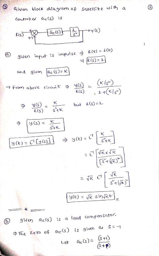
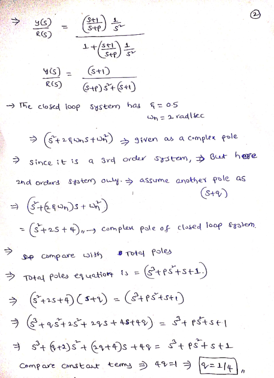
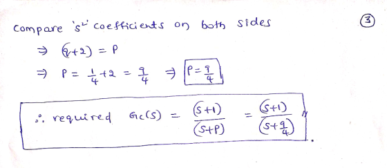
Problem 3: (30 Consider a block diagram which represents the satellite control system with a cont...
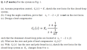
Q. 1 (5 marks) For the system in Fig. (a). Assume proportion control, Gc(s)-K, sketch the root lo...
 pls answer dont just copy other solution or ur catching a
dislike
Q. 1 (5 marks) For the system in Fig. (a). Assume proportion control, Gc(s)-K, sketch the root locus for the closed-loop system (b). Using the angle condition, prove that s12 +j2 is not on the root locus. (c). Design a lead compensator Ge(s) - K such that the dominant closed-loop poles are located at s1--2 2. (d), What are the zero and pole of lead compensator G() (e)....
pls answer dont just copy other solution or ur catching a
dislike
Q. 1 (5 marks) For the system in Fig. (a). Assume proportion control, Gc(s)-K, sketch the root locus for the closed-loop system (b). Using the angle condition, prove that s12 +j2 is not on the root locus. (c). Design a lead compensator Ge(s) - K such that the dominant closed-loop poles are located at s1--2 2. (d), What are the zero and pole of lead compensator G() (e)....
Question 1 (60 points) Consider the following block diagram where G(s)- Controller R(s) G(s) (a) Sketch the root locus assuming a proportional controller is used. [25 points] (b) Design specifica...
 Question 1 (60 points) Consider the following block diagram where G(s)- Controller R(s) G(s) (a) Sketch the root locus assuming a proportional controller is used. [25 points] (b) Design specifications require a closed-loop pole at (-3+j1). Design a lead compensator to make sure the root locus goes through this point. For the design, pick the pole of the compensator at-23 and analytically find its zero. (Hint: Lead compensator transfer function will be Ge (s)$+23 First plot the poles and zeros...
3. Consider the tilt control block diagram shown below R(s) DesiredG(s) 12 s(s+10)(s+70) Y(s) Til...
 3. Consider the tilt control block diagram shown below R(s) DesiredG(s) 12 s(s+10)(s+70) Y(s) Tilt tilt Design specifications require an overshoot of less than 5% and a settling time of less than 0.6 seconds. (a) Use MATLAB to sketch the root locus (rlocus command) with a proportional controller and use the root locus to determine a value for K (if any) that will satisfy the design requirements (b) Design a lead compensator Ge(s) to satisfy the design specifications. You can...
Consider the electro-mechanical feedback control system shown in Figure 3. The voltage Ea(s) - Liea(t)) is...
 Consider the electro-mechanical feedback control system shown in Figure 3. The voltage Ea(s) - Liea(t)) is generated by an amplifier whose transfer function is Ga(s) -5 The position sensor has a transfer function H(s) 1 and the pre-compensator transfer function is pot X (s) Ea(s) The "Electro-Mechanical System" block, is X(s) Ea(s) 5.05s3 101s2 +505.2s 100 R(s) Amplifier, |Ea(S)Electro-MechanicalX(S) Controller, Gc(s) K, pot Ga(s) System, G(s) Encoder H(s) Figure 3: Electro-mechanical control system for Question 3 Consider a proportional controller...
Problem 1: Consider the block functional diagram of the satellite attitude control system shown in Figure...
 Problem 1: Consider the block functional diagram of the satellite attitude control system shown in Figure (a), here below. The output of this system exhibits continued oscillations and is not desirable. This system can be improved by using a tachometer feedback. Ki, as shown in Figure (b). Assuming that = 4, using block diagram algebra and theory of time performance specifications for second order systems, please, compute: (1) the value of the gain K such that closed loop transfer function...
Question 1 (60 points) Consider the following block diagram where G (s) Froarss RMs) GIs) Gls) (a) Sketch the root locus assuming a proportional controller is used. (b) Assume design spocifications r...
 Question 1 (60 points) Consider the following block diagram where G (s) Froarss RMs) GIs) Gls) (a) Sketch the root locus assuming a proportional controller is used. (b) Assume design spocifications require a closed-loop pole at (-3+ j1). Design a lead compensator sure the root locus goes through this point. For the design, pick the pole of the compensator at -23 and analytically find its zero location. (c) Sketch the root locus with the lead compensator in place.
Question 1...
Question 1 (60 points) Consider the following block diagram where G (s) Froarss RMs) GIs) Gls) (a) Sketch the root locus assuming a proportional controller is used. (b) Assume design spocifications require a closed-loop pole at (-3+ j1). Design a lead compensator sure the root locus goes through this point. For the design, pick the pole of the compensator at -23 and analytically find its zero location. (c) Sketch the root locus with the lead compensator in place.
Question 1...
Q. 1 (10 marks) For the system in Fig. 1 (a) Assume proportion control. Ge(s) =...
 Q. 1 (10 marks) For the system in Fig. 1 (a) Assume proportion control. Ge(s) = K. sketch the root locus for the closed-loop system (b). Using the angle condition, prove that s1 =-2 +j2 is not on the root locus. (c). Design a lead compensator such that the dominant closed-loop poles are located at s-2tj2. (d). What are the zero and pole of lead compensator Ge(s)? (e). With Ge (s) has the zero and pole found in (c), sketch...
Consider the automobile cruise-control system shown below: Engine ActuatorCarburetor 0.833 and load 40 3s +1 Compensator R(s)E(s) Ge(s) s +1 -t e(t) Sensor 0.03 1) Derive the closed-loop transfer fun...
 Consider the automobile cruise-control system shown below: Engine ActuatorCarburetor 0.833 and load 40 3s +1 Compensator R(s)E(s) Ge(s) s +1 -t e(t) Sensor 0.03 1) Derive the closed-loop transfer function of V(s)/R(s) when Gc(s)-1 2) Derive the closed-loop transfer function of E(s)/R(s) when Ge(s)-1 3) Plot the time history of the error e(t) of the closed-loop system when r(t) is a unit step input. 4) Plot the root-loci of the uncompensated system (when Gc(s)-1). Mark the closed-loop complex poles on...
pls answer dont just copy other solution or ur catching a dislike Q. 1 (5 marks)...
 pls answer dont just copy other solution or ur catching a
dislike
Q. 1 (5 marks) For the system in Fig. (a). Assume proportion control, Gc(s)-K, sketch the root locus for the closed-loop system (b). Using the angle condition, prove that s12 +j2 is not on the root locus. (c). Design a lead compensator Ge(s) - K such that the dominant closed-loop poles are located at s1--2 2. (d), What are the zero and pole of lead compensator G() (e)....
pls answer dont just copy other solution or ur catching a
dislike
Q. 1 (5 marks) For the system in Fig. (a). Assume proportion control, Gc(s)-K, sketch the root locus for the closed-loop system (b). Using the angle condition, prove that s12 +j2 is not on the root locus. (c). Design a lead compensator Ge(s) - K such that the dominant closed-loop poles are located at s1--2 2. (d), What are the zero and pole of lead compensator G() (e)....
Question 3 (10 +10+10+15 45 marks) E(s) C(s) R(s) Figure 3: Unity feedback control system for Question 3 For the unity...
 Question 3 (10 +10+10+15 45 marks) E(s) C(s) R(s) Figure 3: Unity feedback control system for Question 3 For the unity feedback control system shown in Figure 3, 100 G(S) (s+2)(+10) Page 3 of 7 NEE3201 Examination Paper CRICOS Provider No: 00124k a) Determine the phase margin, the gain crossover frequency, the gain margin, the phase crossover frequency of the system when Gc(s)-1, 10 marks) b) Design a proportional controller Gc(s)-K so that a phase margin of 50° is achieved....
 pls answer dont just copy other solution or ur catching a
dislike
Q. 1 (5 marks) For the system in Fig. (a). Assume proportion control, Gc(s)-K, sketch the root locus for the closed-loop system (b). Using the angle condition, prove that s12 +j2 is not on the root locus. (c). Design a lead compensator Ge(s) - K such that the dominant closed-loop poles are located at s1--2 2. (d), What are the zero and pole of lead compensator G() (e)....
pls answer dont just copy other solution or ur catching a
dislike
Q. 1 (5 marks) For the system in Fig. (a). Assume proportion control, Gc(s)-K, sketch the root locus for the closed-loop system (b). Using the angle condition, prove that s12 +j2 is not on the root locus. (c). Design a lead compensator Ge(s) - K such that the dominant closed-loop poles are located at s1--2 2. (d), What are the zero and pole of lead compensator G() (e)....
 Question 1 (60 points) Consider the following block diagram where G(s)- Controller R(s) G(s) (a) Sketch the root locus assuming a proportional controller is used. [25 points] (b) Design specifications require a closed-loop pole at (-3+j1). Design a lead compensator to make sure the root locus goes through this point. For the design, pick the pole of the compensator at-23 and analytically find its zero. (Hint: Lead compensator transfer function will be Ge (s)$+23 First plot the poles and zeros...
 3. Consider the tilt control block diagram shown below R(s) DesiredG(s) 12 s(s+10)(s+70) Y(s) Tilt tilt Design specifications require an overshoot of less than 5% and a settling time of less than 0.6 seconds. (a) Use MATLAB to sketch the root locus (rlocus command) with a proportional controller and use the root locus to determine a value for K (if any) that will satisfy the design requirements (b) Design a lead compensator Ge(s) to satisfy the design specifications. You can...
 Consider the electro-mechanical feedback control system shown in Figure 3. The voltage Ea(s) - Liea(t)) is generated by an amplifier whose transfer function is Ga(s) -5 The position sensor has a transfer function H(s) 1 and the pre-compensator transfer function is pot X (s) Ea(s) The "Electro-Mechanical System" block, is X(s) Ea(s) 5.05s3 101s2 +505.2s 100 R(s) Amplifier, |Ea(S)Electro-MechanicalX(S) Controller, Gc(s) K, pot Ga(s) System, G(s) Encoder H(s) Figure 3: Electro-mechanical control system for Question 3 Consider a proportional controller...
 Problem 1: Consider the block functional diagram of the satellite attitude control system shown in Figure (a), here below. The output of this system exhibits continued oscillations and is not desirable. This system can be improved by using a tachometer feedback. Ki, as shown in Figure (b). Assuming that = 4, using block diagram algebra and theory of time performance specifications for second order systems, please, compute: (1) the value of the gain K such that closed loop transfer function...
 Question 1 (60 points) Consider the following block diagram where G (s) Froarss RMs) GIs) Gls) (a) Sketch the root locus assuming a proportional controller is used. (b) Assume design spocifications require a closed-loop pole at (-3+ j1). Design a lead compensator sure the root locus goes through this point. For the design, pick the pole of the compensator at -23 and analytically find its zero location. (c) Sketch the root locus with the lead compensator in place.
Question 1...
Question 1 (60 points) Consider the following block diagram where G (s) Froarss RMs) GIs) Gls) (a) Sketch the root locus assuming a proportional controller is used. (b) Assume design spocifications require a closed-loop pole at (-3+ j1). Design a lead compensator sure the root locus goes through this point. For the design, pick the pole of the compensator at -23 and analytically find its zero location. (c) Sketch the root locus with the lead compensator in place.
Question 1...
 Q. 1 (10 marks) For the system in Fig. 1 (a) Assume proportion control. Ge(s) = K. sketch the root locus for the closed-loop system (b). Using the angle condition, prove that s1 =-2 +j2 is not on the root locus. (c). Design a lead compensator such that the dominant closed-loop poles are located at s-2tj2. (d). What are the zero and pole of lead compensator Ge(s)? (e). With Ge (s) has the zero and pole found in (c), sketch...
 Consider the automobile cruise-control system shown below: Engine ActuatorCarburetor 0.833 and load 40 3s +1 Compensator R(s)E(s) Ge(s) s +1 -t e(t) Sensor 0.03 1) Derive the closed-loop transfer function of V(s)/R(s) when Gc(s)-1 2) Derive the closed-loop transfer function of E(s)/R(s) when Ge(s)-1 3) Plot the time history of the error e(t) of the closed-loop system when r(t) is a unit step input. 4) Plot the root-loci of the uncompensated system (when Gc(s)-1). Mark the closed-loop complex poles on...
 pls answer dont just copy other solution or ur catching a
dislike
Q. 1 (5 marks) For the system in Fig. (a). Assume proportion control, Gc(s)-K, sketch the root locus for the closed-loop system (b). Using the angle condition, prove that s12 +j2 is not on the root locus. (c). Design a lead compensator Ge(s) - K such that the dominant closed-loop poles are located at s1--2 2. (d), What are the zero and pole of lead compensator G() (e)....
pls answer dont just copy other solution or ur catching a
dislike
Q. 1 (5 marks) For the system in Fig. (a). Assume proportion control, Gc(s)-K, sketch the root locus for the closed-loop system (b). Using the angle condition, prove that s12 +j2 is not on the root locus. (c). Design a lead compensator Ge(s) - K such that the dominant closed-loop poles are located at s1--2 2. (d), What are the zero and pole of lead compensator G() (e)....
 Question 3 (10 +10+10+15 45 marks) E(s) C(s) R(s) Figure 3: Unity feedback control system for Question 3 For the unity feedback control system shown in Figure 3, 100 G(S) (s+2)(+10) Page 3 of 7 NEE3201 Examination Paper CRICOS Provider No: 00124k a) Determine the phase margin, the gain crossover frequency, the gain margin, the phase crossover frequency of the system when Gc(s)-1, 10 marks) b) Design a proportional controller Gc(s)-K so that a phase margin of 50° is achieved....
Most questions answered within 3 hours.
-
Where is the error in this code sequence?
String s1 = "Hello";
String s2 = "ello";...
asked 11 months ago -
Financial data for Joel de Paris, Inc., for last year
follow:
Joel de Paris, Inc.
Balance...
asked 11 months ago -
Consider this reaction:
Al2(SO4)3 (aq)+ BaCl3
(aq) Al2Cl6 (aq)- +
3BaSO4(s) . What is the...
asked 11 months ago -
Suppose that Savneet is considering increasing her
recent random sample from 20 car rentals to 40...
asked 11 months ago -
Trucks arrive at an unloading terminal at an average rate of 120
per hour.
Trucks arrive...
asked 11 months ago -
Why are methanol and ethanol completely soluble in water while
octanol is not very little soluble....
asked 11 months ago -
A facilities manager at a university reads in a research report
that the mean amount of...
asked 11 months ago -
When the CuSO4 is rehydrated by adding water to the anhydrous
compound, is this an endothermic...
asked 11 months ago -
A ray of sunlight is passing from diamond into crown glass; the
angle of incidence is...
asked 11 months ago -
A block of mass 0.249 kg is placed on top of a light, vertical
spring of...
asked 11 months ago -
how do the kidneys compensate in the presences of acidosis
a) trigger hyperventilate
b) reserve acid...
asked 11 months ago -
Question 501 pts
The rental rate of capital to the firm increases. Which of the
following...
asked 11 months ago