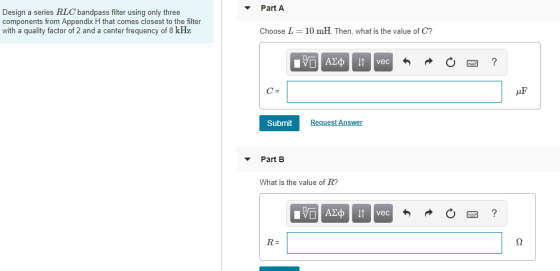
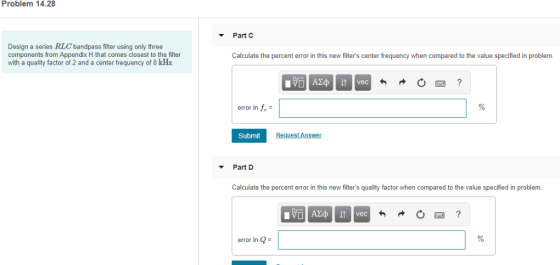
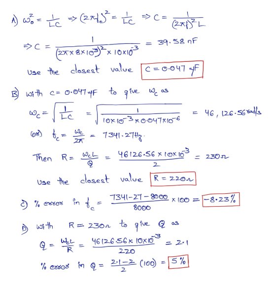
Problem 14.28 Part Design a series RLC bandpass filter using only three components from Appendix H that comes closest to the filter with a quality factor of 2 and a center frequency of 8 kHz. Calculate the percent error in this new filter's center frequency when compared to the value specified in problemm. error in fe Submit ▼ Part D Calculate the percent error in this new filter's quality factor when compared to the value specified in problem vec error in Q
Homework Answers
Add Answer to:
PartA Design a series RLC bandpass filter using only three components from Appendix H that comes ...
Problem 4 Use a 5 nF capacitor to design a series RLC bandpass filter. The center...
 Problem 4 Use a 5 nF capacitor to design a series RLC bandpass filter. The center frequency the filter is 8 kHz, and the quality factor is 1.5. Part A Specify the value of L. View Available Hint(s) EVO AQH vec ? L = 0.079 ml Submit Previous Answers * Incorrect; Try Again; 8 attempts remaining Part B Specify the value of R. 10 AEDIf vec ? R = k12 Submit Request Answer Problem 4 Use a 5 nF capacitor...
Learning Goal: To analyze and design a passive, second-order bandpass filter using a series RLC circuit....
 Learning Goal: To analyze and design a passive, second-order bandpass filter using a series RLC circuit. A bandpass filter is needed for an equalizer, a device that allows one to select the level of amplification of sounds within a specific frequency band while not affecting the sounds outside that band. The filter should block frequencies lower than 1.8 kHz and have a resonant frequency of 5.4 kHz A 3.2 AF capacitor and any needed resistors and inductors are available to...
The center frequency is not given. I believe that it must be find based on the body plot. Problem 6:The Bode plot for a passive series RLC bandpass filter is shown in Fig. 2. This filter was built...
 The center frequency is not given. I believe that it must be
find based on the body plot.
Problem 6:The Bode plot for a passive series RLC bandpass filter is shown in Fig. 2. This filter was built from a 10 μ F capacitor. What is the filter's center frequency, wo, and its quality factor,昱? If you wanted to double the filter's center frequency without changing its quality factor, using the same 10 pu F capacitor, then how would you...
The center frequency is not given. I believe that it must be
find based on the body plot.
Problem 6:The Bode plot for a passive series RLC bandpass filter is shown in Fig. 2. This filter was built from a 10 μ F capacitor. What is the filter's center frequency, wo, and its quality factor,昱? If you wanted to double the filter's center frequency without changing its quality factor, using the same 10 pu F capacitor, then how would you...
Consider the series RLC bandpass filter shown in (Figure 1). The filter has a quality of...
 Consider the series RLC bandpass filter shown in (Figure 1). The filter has a quality of 2 and a center frequency of 8 kHz. The input to the filter is vi (t) = 23 cos wt V. Suppose that C = 5 nF. Figure < 1 of 1 + VLC с L HE + + Vi R} R V. Part E Find the voltage drop across the series combination of the inductor and capacitor when w=10w, Suppose that vlc (t)...
1. Design a parallel RLC bandpass filter, derive the transfer function H(s). Compute the center frequency, Wo. Calculate the cutoff frequencies Wej and Wc2, the bandwidth ß, and quality factor, Q. Co...
 1. Design a parallel RLC bandpass filter, derive the transfer function H(s). Compute the center frequency, Wo. Calculate the cutoff frequencies Wej and Wc2, the bandwidth ß, and quality factor, Q. Compute values for R and L to yield a bandpass filter with a center frequency of 5kHz and a bandwidth of 200Hz, using a 10nF capacitor. (25 points)
1. Design a parallel RLC bandpass filter, derive the transfer function H(s). Compute the center frequency, Wo. Calculate the cutoff frequencies...
1. Design a parallel RLC bandpass filter, derive the transfer function H(s). Compute the center frequency, Wo. Calculate the cutoff frequencies Wej and Wc2, the bandwidth ß, and quality factor, Q. Compute values for R and L to yield a bandpass filter with a center frequency of 5kHz and a bandwidth of 200Hz, using a 10nF capacitor. (25 points)
1. Design a parallel RLC bandpass filter, derive the transfer function H(s). Compute the center frequency, Wo. Calculate the cutoff frequencies...
Scale the bandpass filter in (Figure 1) so that the center frequency is 180 kHz and...
 Scale the bandpass filter in (Figure 1) so that the center frequency is 180 kHz and the quality factor is 8, using a 2.5 nF capacitor. Figure < 1 of 1 > 8k 310 mH 10 nF Part A Determine the value of the resistor of the scaled filter Express your answer to three significant figures and include the appropriate units. R = Value Units Submit Request Answer Part B Determine the value of the inductor of the scaled filter...
1. Design the following series RLC filter (find values of R and L) with a quality...
 1. Design the following series RLC filter (find values of R and L) with a quality factor of 5 and a center frequency of 20 krad / s. For the filter that you designed, find the bandwidth and the values of two cutoff frequencies 0.05 HF L
We would like to build an AM radio receiver using a series RLC circuit working as a bandpass filter. We have decided to...
 We would like to build an AM radio receiver using a series RLC
circuit working as a bandpass filter. We have decided to use a 240
μH inductor with an internal resistance of 12Ω, and a variable
capacitor whose capacitance varies between 40 to 360 pF. A radio
“tunes” into a certain frequency by adjusting its receiver circuit
so that it resonates at that frequency, and it only catches that
specific frequency.
1. Determine the range of channel frequencies that...
We would like to build an AM radio receiver using a series RLC
circuit working as a bandpass filter. We have decided to use a 240
μH inductor with an internal resistance of 12Ω, and a variable
capacitor whose capacitance varies between 40 to 360 pF. A radio
“tunes” into a certain frequency by adjusting its receiver circuit
so that it resonates at that frequency, and it only catches that
specific frequency.
1. Determine the range of channel frequencies that...
Homework #2 Problem 14.38 PSpice Multisim Part A Consider the bandreject filter shown in (Figure 1)....
 Homework #2 Problem 14.38 PSpice Multisim Part A Consider the bandreject filter shown in (Figure 1). Suppose that R-4 k2,L-3.5 mH, C-62.5 nF Calculate the center frequency wo. Express your answer using three significant figures vec krad/s Figure 1 of 1 Submit Request Answen Part B Calculate the center frequency f, in kilohertz. Express your answer using three significant figures vec kHz Problem 14.38 PSpice Multisim Part C Consider the bandreject filter shown in (Figure 1). Suppose that R-4 k2,L-3.5...
Analysis and Design of Bandpass Filters 3 of Re View Available Hints) 12-16.20 kH Learning Goal:...
 Analysis and Design of Bandpass Filters 3 of Re View Available Hints) 12-16.20 kH Learning Goal: To analyze and design a passive, second-order bandpass filter using a series RLC circut A bandpass literis needed for an equalizer, a device that allows one to select the level of amplification of sounds within a specific trequency band while not affecting the sounds outside that band. The fitor should block frequencies lower than 1.8 kHz and have a resonant frequency of 5.4 kHz....
 Problem 4 Use a 5 nF capacitor to design a series RLC bandpass filter. The center frequency the filter is 8 kHz, and the quality factor is 1.5. Part A Specify the value of L. View Available Hint(s) EVO AQH vec ? L = 0.079 ml Submit Previous Answers * Incorrect; Try Again; 8 attempts remaining Part B Specify the value of R. 10 AEDIf vec ? R = k12 Submit Request Answer Problem 4 Use a 5 nF capacitor...
 Learning Goal: To analyze and design a passive, second-order bandpass filter using a series RLC circuit. A bandpass filter is needed for an equalizer, a device that allows one to select the level of amplification of sounds within a specific frequency band while not affecting the sounds outside that band. The filter should block frequencies lower than 1.8 kHz and have a resonant frequency of 5.4 kHz A 3.2 AF capacitor and any needed resistors and inductors are available to...
 The center frequency is not given. I believe that it must be
find based on the body plot.
Problem 6:The Bode plot for a passive series RLC bandpass filter is shown in Fig. 2. This filter was built from a 10 μ F capacitor. What is the filter's center frequency, wo, and its quality factor,昱? If you wanted to double the filter's center frequency without changing its quality factor, using the same 10 pu F capacitor, then how would you...
The center frequency is not given. I believe that it must be
find based on the body plot.
Problem 6:The Bode plot for a passive series RLC bandpass filter is shown in Fig. 2. This filter was built from a 10 μ F capacitor. What is the filter's center frequency, wo, and its quality factor,昱? If you wanted to double the filter's center frequency without changing its quality factor, using the same 10 pu F capacitor, then how would you...
 Consider the series RLC bandpass filter shown in (Figure 1). The filter has a quality of 2 and a center frequency of 8 kHz. The input to the filter is vi (t) = 23 cos wt V. Suppose that C = 5 nF. Figure < 1 of 1 + VLC с L HE + + Vi R} R V. Part E Find the voltage drop across the series combination of the inductor and capacitor when w=10w, Suppose that vlc (t)...
 1. Design a parallel RLC bandpass filter, derive the transfer function H(s). Compute the center frequency, Wo. Calculate the cutoff frequencies Wej and Wc2, the bandwidth ß, and quality factor, Q. Compute values for R and L to yield a bandpass filter with a center frequency of 5kHz and a bandwidth of 200Hz, using a 10nF capacitor. (25 points)
1. Design a parallel RLC bandpass filter, derive the transfer function H(s). Compute the center frequency, Wo. Calculate the cutoff frequencies...
1. Design a parallel RLC bandpass filter, derive the transfer function H(s). Compute the center frequency, Wo. Calculate the cutoff frequencies Wej and Wc2, the bandwidth ß, and quality factor, Q. Compute values for R and L to yield a bandpass filter with a center frequency of 5kHz and a bandwidth of 200Hz, using a 10nF capacitor. (25 points)
1. Design a parallel RLC bandpass filter, derive the transfer function H(s). Compute the center frequency, Wo. Calculate the cutoff frequencies...
 Scale the bandpass filter in (Figure 1) so that the center frequency is 180 kHz and the quality factor is 8, using a 2.5 nF capacitor. Figure < 1 of 1 > 8k 310 mH 10 nF Part A Determine the value of the resistor of the scaled filter Express your answer to three significant figures and include the appropriate units. R = Value Units Submit Request Answer Part B Determine the value of the inductor of the scaled filter...
 1. Design the following series RLC filter (find values of R and L) with a quality factor of 5 and a center frequency of 20 krad / s. For the filter that you designed, find the bandwidth and the values of two cutoff frequencies 0.05 HF L
 We would like to build an AM radio receiver using a series RLC
circuit working as a bandpass filter. We have decided to use a 240
μH inductor with an internal resistance of 12Ω, and a variable
capacitor whose capacitance varies between 40 to 360 pF. A radio
“tunes” into a certain frequency by adjusting its receiver circuit
so that it resonates at that frequency, and it only catches that
specific frequency.
1. Determine the range of channel frequencies that...
We would like to build an AM radio receiver using a series RLC
circuit working as a bandpass filter. We have decided to use a 240
μH inductor with an internal resistance of 12Ω, and a variable
capacitor whose capacitance varies between 40 to 360 pF. A radio
“tunes” into a certain frequency by adjusting its receiver circuit
so that it resonates at that frequency, and it only catches that
specific frequency.
1. Determine the range of channel frequencies that...
 Homework #2 Problem 14.38 PSpice Multisim Part A Consider the bandreject filter shown in (Figure 1). Suppose that R-4 k2,L-3.5 mH, C-62.5 nF Calculate the center frequency wo. Express your answer using three significant figures vec krad/s Figure 1 of 1 Submit Request Answen Part B Calculate the center frequency f, in kilohertz. Express your answer using three significant figures vec kHz Problem 14.38 PSpice Multisim Part C Consider the bandreject filter shown in (Figure 1). Suppose that R-4 k2,L-3.5...
 Analysis and Design of Bandpass Filters 3 of Re View Available Hints) 12-16.20 kH Learning Goal: To analyze and design a passive, second-order bandpass filter using a series RLC circut A bandpass literis needed for an equalizer, a device that allows one to select the level of amplification of sounds within a specific trequency band while not affecting the sounds outside that band. The fitor should block frequencies lower than 1.8 kHz and have a resonant frequency of 5.4 kHz....
Most questions answered within 3 hours.
-
Where is the error in this code sequence?
String s1 = "Hello";
String s2 = "ello";...
asked 11 months ago -
Financial data for Joel de Paris, Inc., for last year
follow:
Joel de Paris, Inc.
Balance...
asked 11 months ago -
Consider this reaction:
Al2(SO4)3 (aq)+ BaCl3
(aq) Al2Cl6 (aq)- +
3BaSO4(s) . What is the...
asked 11 months ago -
Suppose that Savneet is considering increasing her
recent random sample from 20 car rentals to 40...
asked 11 months ago -
Trucks arrive at an unloading terminal at an average rate of 120
per hour.
Trucks arrive...
asked 11 months ago -
Why are methanol and ethanol completely soluble in water while
octanol is not very little soluble....
asked 11 months ago -
A facilities manager at a university reads in a research report
that the mean amount of...
asked 11 months ago -
When the CuSO4 is rehydrated by adding water to the anhydrous
compound, is this an endothermic...
asked 11 months ago -
A ray of sunlight is passing from diamond into crown glass; the
angle of incidence is...
asked 11 months ago -
A block of mass 0.249 kg is placed on top of a light, vertical
spring of...
asked 11 months ago -
how do the kidneys compensate in the presences of acidosis
a) trigger hyperventilate
b) reserve acid...
asked 11 months ago -
Question 501 pts
The rental rate of capital to the firm increases. Which of the
following...
asked 11 months ago