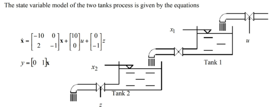
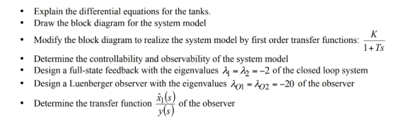
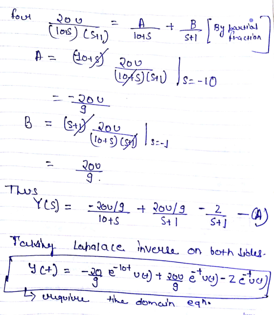
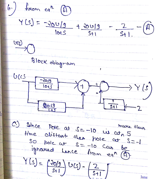
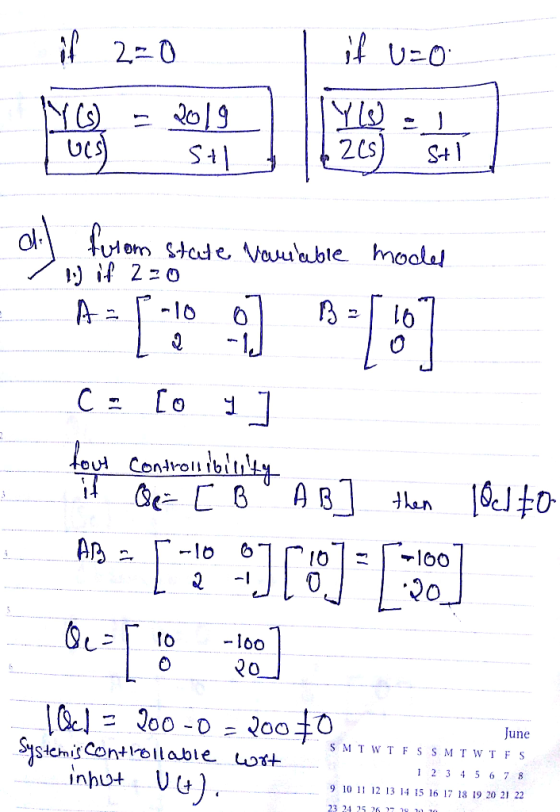
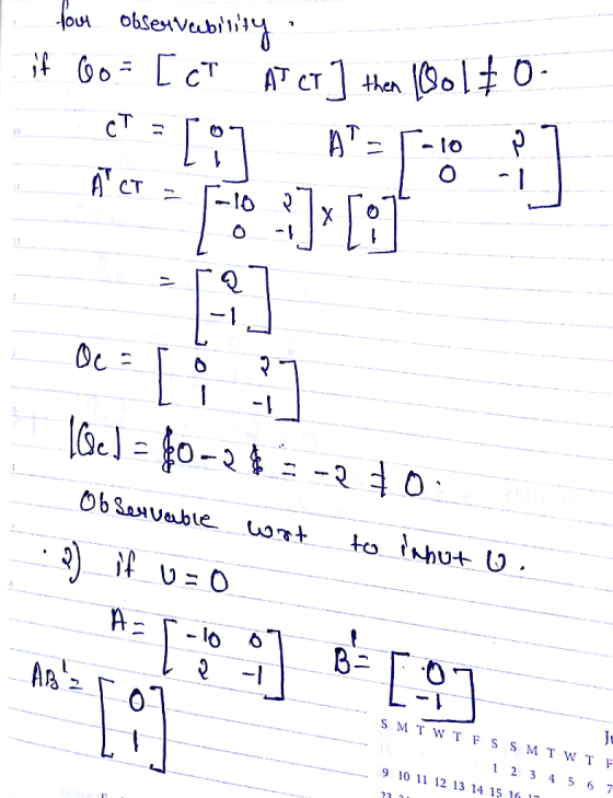
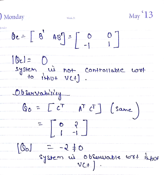
Explain the differential equations for the tanks Draw the block diagram for the system model * .Modify the block diagram to realize the system model by first order transfer functions: 1+Ts Determine the controllability and observability of the system model Design a full-state feedback with the eigen values λ-λ2--2 of the closed loop system Design a Luenberger observer with the eigenvalues Determine the transfer functionof . . o2 -20 of the observer h(s) y(s the observer
Homework Answers
Add Answer to:
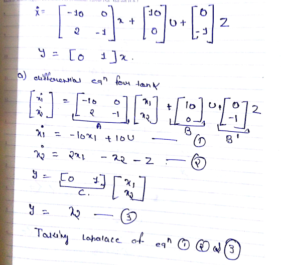
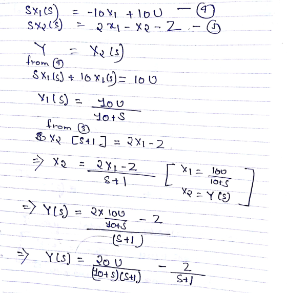
The state variable model of the two tanks process is given by the equations r1 10 01 r1o 2 0-1 lu Tank 1 Tank 2 Explain the differential equations for the tanks Draw the block diagram for the system...
Consider the following system: -1-2-21 гг 1 0 1 L Where u is the system input and y is the measur...
 control system with observer
Consider the following system: -1-2-21 гг 1 0 1 L Where u is the system input and y is the measured output. 1. Find the transfer function of the system. 2. Design a state feedback controller with a full-state observer such that the step response of the closed loop system is second order dominant with an overshoot Mp settling time ts s 5 sec. Represent the observer-based control system in a compact state space form. 10%...
control system with observer
Consider the following system: -1-2-21 гг 1 0 1 L Where u is the system input and y is the measured output. 1. Find the transfer function of the system. 2. Design a state feedback controller with a full-state observer such that the step response of the closed loop system is second order dominant with an overshoot Mp settling time ts s 5 sec. Represent the observer-based control system in a compact state space form. 10%...
Consider a two-tank system, where x, is the level of the first tank, and x2 is the level of the second tank. This dynamic system is described by the -xj-x2. The output to be Q4. following model: dt c...
 Consider a two-tank system, where x, is the level of the first tank, and x2 is the level of the second tank. This dynamic system is described by the -xj-x2. The output to be Q4. following model: dt controlled is the level of the second tank. (a)Write down the state-space model in matrix form. Verify the 20% (b)Design a state feedback controller so that the closed-loop poles are 25% controllability of the system located at -3 and -4 (c) The...
The state space model of an interconnected three tank water storage system is given by the following equation: -3 1 0 1rh dt os lo 0 3] 10 1-3 The heights of water in the tanks are, respectively,...
 The state space model of an interconnected three tank water storage system is given by the following equation: -3 1 0 1rh dt os lo 0 3] 10 1-3 The heights of water in the tanks are, respectively, h,h2,h3. Each tank has an independent input flow; the volume flow rates of input water into the three tanks are, respectively, qǐ1,W2,4a. Each tank also has a water discharge outlet and the volume flow rates of water coming out of the tanks...
1- A system has a block diagram as shown. Determine a state variable representation (model) and...
 1- A system has a block diagram as shown. Determine a state variable representation (model) and state transition matrix Φ(s) R(s) + 25 Y(s) 25 2- A system has the following differential equation: 2 -3 Determine Ф(t) and its transform D(s) for the system
The state space model of an interconnected three tank water storage system is given by the following equation -3 1 o 1[hi] dt The heights of water in the tanks are, respectively, hi, h2, hz. Each tan...
 The state space model of an interconnected three tank water storage system is given by the following equation -3 1 o 1[hi] dt The heights of water in the tanks are, respectively, hi, h2, hz. Each tank has an independent input flow; the volume flow rates of input water into the three tanks are, respectively, qii,qi2, Oi3. Each tank also has a water discharge outlet and the volume flow rates of water coming out of the tanks are, respectively, qo1,...
3. The transfer function of a control system is given as G(s) = (s+1)(s+2)(s45) (a) Determine a state variable representation in observer canonical form. (b) Design a full order observer of the syste...
 3. The transfer function of a control system is given as G(s) = (s+1)(s+2)(s45) (a) Determine a state variable representation in observer canonical form. (b) Design a full order observer of the system. Let the poles of the observer be 10 times faster than the system poles. Show the observer gain matrix. (c) Determine and plot the errors responses between the estimated output and the actual output. (d) Determine and plot the estimated state variables and determine their settling times....
A system is described by the state variable equations 0 -2 1 10 y(t) =[1 0...
 A system is described by the state variable equations 0 -2 1 10 y(t) =[1 0 (ls(t). Determine G(s) = r(s)/U(s).
control system System Description: The figure 1 and 2 below show, respectively, components and block diagram...
 control system
System Description: The figure 1 and 2 below show, respectively, components and block diagram of a motor and the measurements of velocity (via the tacho unit) and position (via the potentiometer). n represents the gearbox ratio between the rotating shaft and the output shaft. The left-hand side of the diagram represents the controller. A reference set point for the rotating shaft is entered in degrees and this is equivalent voltage. The error is calculated by subtracting the measured...
control system
System Description: The figure 1 and 2 below show, respectively, components and block diagram of a motor and the measurements of velocity (via the tacho unit) and position (via the potentiometer). n represents the gearbox ratio between the rotating shaft and the output shaft. The left-hand side of the diagram represents the controller. A reference set point for the rotating shaft is entered in degrees and this is equivalent voltage. The error is calculated by subtracting the measured...
 control system with observer
Consider the following system: -1-2-21 гг 1 0 1 L Where u is the system input and y is the measured output. 1. Find the transfer function of the system. 2. Design a state feedback controller with a full-state observer such that the step response of the closed loop system is second order dominant with an overshoot Mp settling time ts s 5 sec. Represent the observer-based control system in a compact state space form. 10%...
control system with observer
Consider the following system: -1-2-21 гг 1 0 1 L Where u is the system input and y is the measured output. 1. Find the transfer function of the system. 2. Design a state feedback controller with a full-state observer such that the step response of the closed loop system is second order dominant with an overshoot Mp settling time ts s 5 sec. Represent the observer-based control system in a compact state space form. 10%...
 Consider a two-tank system, where x, is the level of the first tank, and x2 is the level of the second tank. This dynamic system is described by the -xj-x2. The output to be Q4. following model: dt controlled is the level of the second tank. (a)Write down the state-space model in matrix form. Verify the 20% (b)Design a state feedback controller so that the closed-loop poles are 25% controllability of the system located at -3 and -4 (c) The...
 The state space model of an interconnected three tank water storage system is given by the following equation: -3 1 0 1rh dt os lo 0 3] 10 1-3 The heights of water in the tanks are, respectively, h,h2,h3. Each tank has an independent input flow; the volume flow rates of input water into the three tanks are, respectively, qǐ1,W2,4a. Each tank also has a water discharge outlet and the volume flow rates of water coming out of the tanks...
 1- A system has a block diagram as shown. Determine a state variable representation (model) and state transition matrix Φ(s) R(s) + 25 Y(s) 25 2- A system has the following differential equation: 2 -3 Determine Ф(t) and its transform D(s) for the system
 The state space model of an interconnected three tank water storage system is given by the following equation -3 1 o 1[hi] dt The heights of water in the tanks are, respectively, hi, h2, hz. Each tank has an independent input flow; the volume flow rates of input water into the three tanks are, respectively, qii,qi2, Oi3. Each tank also has a water discharge outlet and the volume flow rates of water coming out of the tanks are, respectively, qo1,...
 3. The transfer function of a control system is given as G(s) = (s+1)(s+2)(s45) (a) Determine a state variable representation in observer canonical form. (b) Design a full order observer of the system. Let the poles of the observer be 10 times faster than the system poles. Show the observer gain matrix. (c) Determine and plot the errors responses between the estimated output and the actual output. (d) Determine and plot the estimated state variables and determine their settling times....
 A system is described by the state variable equations 0 -2 1 10 y(t) =[1 0 (ls(t). Determine G(s) = r(s)/U(s).
 control system
System Description: The figure 1 and 2 below show, respectively, components and block diagram of a motor and the measurements of velocity (via the tacho unit) and position (via the potentiometer). n represents the gearbox ratio between the rotating shaft and the output shaft. The left-hand side of the diagram represents the controller. A reference set point for the rotating shaft is entered in degrees and this is equivalent voltage. The error is calculated by subtracting the measured...
control system
System Description: The figure 1 and 2 below show, respectively, components and block diagram of a motor and the measurements of velocity (via the tacho unit) and position (via the potentiometer). n represents the gearbox ratio between the rotating shaft and the output shaft. The left-hand side of the diagram represents the controller. A reference set point for the rotating shaft is entered in degrees and this is equivalent voltage. The error is calculated by subtracting the measured...
Most questions answered within 3 hours.
-
Where is the error in this code sequence?
String s1 = "Hello";
String s2 = "ello";...
asked 11 months ago -
Financial data for Joel de Paris, Inc., for last year
follow:
Joel de Paris, Inc.
Balance...
asked 11 months ago -
Consider this reaction:
Al2(SO4)3 (aq)+ BaCl3
(aq) Al2Cl6 (aq)- +
3BaSO4(s) . What is the...
asked 11 months ago -
Suppose that Savneet is considering increasing her
recent random sample from 20 car rentals to 40...
asked 11 months ago -
Trucks arrive at an unloading terminal at an average rate of 120
per hour.
Trucks arrive...
asked 11 months ago -
Why are methanol and ethanol completely soluble in water while
octanol is not very little soluble....
asked 11 months ago -
A facilities manager at a university reads in a research report
that the mean amount of...
asked 11 months ago -
When the CuSO4 is rehydrated by adding water to the anhydrous
compound, is this an endothermic...
asked 11 months ago -
A ray of sunlight is passing from diamond into crown glass; the
angle of incidence is...
asked 11 months ago -
A block of mass 0.249 kg is placed on top of a light, vertical
spring of...
asked 11 months ago -
how do the kidneys compensate in the presences of acidosis
a) trigger hyperventilate
b) reserve acid...
asked 11 months ago -
Question 501 pts
The rental rate of capital to the firm increases. Which of the
following...
asked 11 months ago