
Homework Answers
Add Answer to:
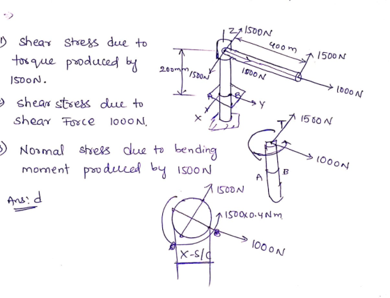
What stresses would you need to calculate in order to develop the 2D state of stress for point B on the cross section of the pipe assembly 400 mm al 200 mm 1500 N 1000 N 20 mm Section a-a a. Normal s...
Learning Goal: To calculate the normal and shear stresses at a point on the cross section...
 Learning Goal: To calculate the normal and shear stresses at a point on the cross section of a column. The state of stress at a point is a description of the normal and shear stresses at that point. The normal stresses are generally due to both internal normal force and internal bending moment. The net result can be obtained using the principle of superposition as long as the deflections remain small and the response is elastic. Figure < 1 of...
For the pipe assembly shown below, a) determine the internal loads in section a-a b) identify...
 For the pipe assembly shown below, a) determine the internal loads in section a-a b) identify the types of loads (axial, bending, torsion, etc...) c) determine the state of stress at point A d) show the results in a differential volumetric element at A. 400 mm 200 mm 1500 N 20 mm 1000 N Section a-a
A column with a wide-flange section has a flange width b = 400 mm , height...
 A column with a wide-flange section has a flange width
b = 400 mm , height h = 400 mm , web thickness
tw = 13 mm , and flange thickness
tf = 21 mm (Figure 1). Calculate the stresses at
a point 65 mm above the neutral axis if the section supports a
tensile normal force N = 3 kN at the centroid, shear force
V = 7.4 kN , and bending moment M = 4 kN⋅m as
shown...
A column with a wide-flange section has a flange width
b = 400 mm , height h = 400 mm , web thickness
tw = 13 mm , and flange thickness
tf = 21 mm (Figure 1). Calculate the stresses at
a point 65 mm above the neutral axis if the section supports a
tensile normal force N = 3 kN at the centroid, shear force
V = 7.4 kN , and bending moment M = 4 kN⋅m as
shown...
Determine the state of stress at point A on the cross section of the pipe assembly...
 Determine the state of stress at point A on the cross section of the pipe assembly at section a-a. Take Fi = 1480 N. F2 = 1090 N (Figure 1) Express your answer to three significant figures and include the appropriate units. Enter negative value in the case of compression and positive in the case of tension. НА ? Figure < 1 of 1 Value Units Submit Request Answer 400 mm Part B 200 mm Fi Find (Tay) Express your...
1. The part shown consists of a bent rod with a solid circular cross section of...
 1. The part shown consists of a bent rod with a solid circular cross section of diameter 20 mm. Consider the cross- section on a cut at both a-a, and b-b. 400 mm A] For each cut, label the shear force, bending moments, and torsion moments. Then determine the critical point with the highest normal stress at each cross- section. No stress calculations are required. /100 mm 1 BJ Determine the point of highest normal stress for the bent rod...
7) Given the state of stress at point A on the circular cross section a-a of...
 7) Given the state of stress at point A on the circular cross section a-a of the handle assembly is oz 47.11 MPa, ryz = 48.81 MPa. Show the results on the volume element shown. 800 N 400 mm 200 mm 1500 N 20 mm1000 N Section a-a
10 mm 10 mm 300 N/m 50 mm 10 mm Problem 2. Consider the beam above with the cross-section shown. ...
 please solve 1-5 and show all steps and equations used
10 mm 10 mm 300 N/m 50 mm 10 mm Problem 2. Consider the beam above with the cross-section shown. The number (300N/m) indicates the value of the load distribution at its peak. (5 pts.) Find the reactions (15 pts.) Draw the shear and moment diagrams using the graphical method. Ensure you state values of the diagrams, and type of function for lincar or higher-order segments. You can indicate all...
please solve 1-5 and show all steps and equations used
10 mm 10 mm 300 N/m 50 mm 10 mm Problem 2. Consider the beam above with the cross-section shown. The number (300N/m) indicates the value of the load distribution at its peak. (5 pts.) Find the reactions (15 pts.) Draw the shear and moment diagrams using the graphical method. Ensure you state values of the diagrams, and type of function for lincar or higher-order segments. You can indicate all...
1) For the loading of the beam shown below, determine the maximum normal and shear stress...
 1) For the loading of the beam shown below, determine the maximum normal and shear stress at the wall if Kt for bending is 2.7 and K, for torsion is 2.3 If we use a steel with an Sy 600 MPa, what is the "safety factor" if we only consider the maximum normal stress? Notice the bending moment, start with a cross product to determine the moment at the wall. The vector R-[0.25,0,0.3] in meters 200 mm 25-mm-dia. round rod...
Problem 1: A shaft, with a diameter of 43 mm, is shown below. On the right-hand side at location ...
 Problem 1: A shaft, with a diameter of 43 mm, is shown below. On the right-hand side at location D a wheel has a force F of 4824N applied. The diameter of this wheel is 150 mm. The torque produced by F is transmitted through the entire shaft to location A where the torque is reacted. There are no other constraints at location A. Bearings, are located at B and C, and provide radial constraint. The bearing at B also...
PROBLEM 2: 40% A 6 kN force is exerted on the frame which has the T cross sectio analyze the states of stress at a section taken at 800 mm from the point of n shown below. It is required to 1. Fo...
 PROBLEM 2: 40% A 6 kN force is exerted on the frame which has the T cross sectio analyze the states of stress at a section taken at 800 mm from the point of n shown below. It is required to 1. For the given T cross section, find the centroid and the area moment of inertia I,. 2. Draw the free body diagram of the free end of the frame and determine the interna loadings at the centroid of...
 Learning Goal: To calculate the normal and shear stresses at a point on the cross section of a column. The state of stress at a point is a description of the normal and shear stresses at that point. The normal stresses are generally due to both internal normal force and internal bending moment. The net result can be obtained using the principle of superposition as long as the deflections remain small and the response is elastic. Figure < 1 of...
 For the pipe assembly shown below, a) determine the internal loads in section a-a b) identify the types of loads (axial, bending, torsion, etc...) c) determine the state of stress at point A d) show the results in a differential volumetric element at A. 400 mm 200 mm 1500 N 20 mm 1000 N Section a-a
 A column with a wide-flange section has a flange width
b = 400 mm , height h = 400 mm , web thickness
tw = 13 mm , and flange thickness
tf = 21 mm (Figure 1). Calculate the stresses at
a point 65 mm above the neutral axis if the section supports a
tensile normal force N = 3 kN at the centroid, shear force
V = 7.4 kN , and bending moment M = 4 kN⋅m as
shown...
A column with a wide-flange section has a flange width
b = 400 mm , height h = 400 mm , web thickness
tw = 13 mm , and flange thickness
tf = 21 mm (Figure 1). Calculate the stresses at
a point 65 mm above the neutral axis if the section supports a
tensile normal force N = 3 kN at the centroid, shear force
V = 7.4 kN , and bending moment M = 4 kN⋅m as
shown...
 Determine the state of stress at point A on the cross section of the pipe assembly at section a-a. Take Fi = 1480 N. F2 = 1090 N (Figure 1) Express your answer to three significant figures and include the appropriate units. Enter negative value in the case of compression and positive in the case of tension. НА ? Figure < 1 of 1 Value Units Submit Request Answer 400 mm Part B 200 mm Fi Find (Tay) Express your...
 1. The part shown consists of a bent rod with a solid circular cross section of diameter 20 mm. Consider the cross- section on a cut at both a-a, and b-b. 400 mm A] For each cut, label the shear force, bending moments, and torsion moments. Then determine the critical point with the highest normal stress at each cross- section. No stress calculations are required. /100 mm 1 BJ Determine the point of highest normal stress for the bent rod...
 7) Given the state of stress at point A on the circular cross section a-a of the handle assembly is oz 47.11 MPa, ryz = 48.81 MPa. Show the results on the volume element shown. 800 N 400 mm 200 mm 1500 N 20 mm1000 N Section a-a
 please solve 1-5 and show all steps and equations used
10 mm 10 mm 300 N/m 50 mm 10 mm Problem 2. Consider the beam above with the cross-section shown. The number (300N/m) indicates the value of the load distribution at its peak. (5 pts.) Find the reactions (15 pts.) Draw the shear and moment diagrams using the graphical method. Ensure you state values of the diagrams, and type of function for lincar or higher-order segments. You can indicate all...
please solve 1-5 and show all steps and equations used
10 mm 10 mm 300 N/m 50 mm 10 mm Problem 2. Consider the beam above with the cross-section shown. The number (300N/m) indicates the value of the load distribution at its peak. (5 pts.) Find the reactions (15 pts.) Draw the shear and moment diagrams using the graphical method. Ensure you state values of the diagrams, and type of function for lincar or higher-order segments. You can indicate all...
 1) For the loading of the beam shown below, determine the maximum normal and shear stress at the wall if Kt for bending is 2.7 and K, for torsion is 2.3 If we use a steel with an Sy 600 MPa, what is the "safety factor" if we only consider the maximum normal stress? Notice the bending moment, start with a cross product to determine the moment at the wall. The vector R-[0.25,0,0.3] in meters 200 mm 25-mm-dia. round rod...
 Problem 1: A shaft, with a diameter of 43 mm, is shown below. On the right-hand side at location D a wheel has a force F of 4824N applied. The diameter of this wheel is 150 mm. The torque produced by F is transmitted through the entire shaft to location A where the torque is reacted. There are no other constraints at location A. Bearings, are located at B and C, and provide radial constraint. The bearing at B also...
 PROBLEM 2: 40% A 6 kN force is exerted on the frame which has the T cross sectio analyze the states of stress at a section taken at 800 mm from the point of n shown below. It is required to 1. For the given T cross section, find the centroid and the area moment of inertia I,. 2. Draw the free body diagram of the free end of the frame and determine the interna loadings at the centroid of...
Most questions answered within 3 hours.
-
Where is the error in this code sequence?
String s1 = "Hello";
String s2 = "ello";...
asked 11 months ago -
Financial data for Joel de Paris, Inc., for last year
follow:
Joel de Paris, Inc.
Balance...
asked 11 months ago -
Consider this reaction:
Al2(SO4)3 (aq)+ BaCl3
(aq) Al2Cl6 (aq)- +
3BaSO4(s) . What is the...
asked 11 months ago -
Suppose that Savneet is considering increasing her
recent random sample from 20 car rentals to 40...
asked 11 months ago -
Trucks arrive at an unloading terminal at an average rate of 120
per hour.
Trucks arrive...
asked 11 months ago -
Why are methanol and ethanol completely soluble in water while
octanol is not very little soluble....
asked 11 months ago -
A facilities manager at a university reads in a research report
that the mean amount of...
asked 11 months ago -
When the CuSO4 is rehydrated by adding water to the anhydrous
compound, is this an endothermic...
asked 11 months ago -
A ray of sunlight is passing from diamond into crown glass; the
angle of incidence is...
asked 11 months ago -
A block of mass 0.249 kg is placed on top of a light, vertical
spring of...
asked 11 months ago -
how do the kidneys compensate in the presences of acidosis
a) trigger hyperventilate
b) reserve acid...
asked 11 months ago -
Question 501 pts
The rental rate of capital to the firm increases. Which of the
following...
asked 11 months ago