
Homework Answers


1)matlab code and result
clear;clc;
%% part (a)
Gpl=tf([1],[1 1 0]);
Ls1=Gpl*1;
figure(1);
rlocus(Ls1);
title('Rootlocus plot for proportional controller');
%% part (c)
k1=32.14;
M1=feedback(k1*Ls1,1);
figure(2);
step(M1);
title('step response for proportional controller at required
tr');
%% part (d)
Dcl=tf([1 10],[1 71.36]);
Ls2=Gpl*Dcl;
figure(3);
rlocus(Ls2);
title('Rootlocus plot for lead compensator');
k2=767.05;
M2=feedback(k2*Ls2,1);
figure(4);
step(M2);
title('step response for lead compensator at required tr');


if you compare both step response the lead compensated response have small rise time and small overshoot
Add Answer to:
Problem 2 Wis) R(s) U(s) Gol (s) D a (s) E(s) H(s) Given a system as in the diagram above, use MATLAB to solve the problems: Assume we want the closed-loop system rise time to be t, 0.18 sec S + Z H(...
Please solve part b and c and d !! Consider the closed loop system shown in...
 Please solve part b and c and d !!
Consider the closed loop system shown in Figure 4. The root locus of that system is shown in Figure 5 (s+40s+8) R(s) Y(s) Figure 4 System block diagram of Problem 4 a) On the root locus plot, sketch the region of possible roots of the dominant closed-loop poles such that the system response to a unit step has the following time domain specifications. [5] i. Damping ratio, 20.76 ii. Natural frequency,....
Please solve part b and c and d !!
Consider the closed loop system shown in Figure 4. The root locus of that system is shown in Figure 5 (s+40s+8) R(s) Y(s) Figure 4 System block diagram of Problem 4 a) On the root locus plot, sketch the region of possible roots of the dominant closed-loop poles such that the system response to a unit step has the following time domain specifications. [5] i. Damping ratio, 20.76 ii. Natural frequency,....
Wis) R(s u(s) 14 Gl(s) H(s) Given a system as in the diagram above, where K is an adjustable pa...
 Wis) R(s u(s) 14 Gl(s) H(s) Given a system as in the diagram above, where K is an adjustable parameter pl(s) Dal(sKp+ g) Assuming W-0, find the transfer function Y(s)/R(s) h) Assuming R-0, find the transfer function Y(s)/W(s) i) What is the type of the system (with respect to steady-state error)? j) What is the steady-state error when rt)u(t) (unit-step) and w(t)-0 k) What is the s.s. error when r(t) t u(t) and w(t)-0 ) Assume r(t)-0, what is the...
only b and c please 1 Consider the system whose transfer function is given by: G(S)...
 only b and c please
1 Consider the system whose transfer function is given by: G(S) == (2s +1)(s+3) unction is given by: G(s) - (a) Use the root-locus design methodology to design a lead compensator that will provide a closed-loop damping 5 =0.4 and a natural frequency on =9 rad/sec. The general transfer function for lead compensation is given by D(5)=K (977), p>z, 2=2 (b) Use MATLAB to plot the root locus of the feed-forward transfer function, D(s)*G(s), and...
only b and c please
1 Consider the system whose transfer function is given by: G(S) == (2s +1)(s+3) unction is given by: G(s) - (a) Use the root-locus design methodology to design a lead compensator that will provide a closed-loop damping 5 =0.4 and a natural frequency on =9 rad/sec. The general transfer function for lead compensation is given by D(5)=K (977), p>z, 2=2 (b) Use MATLAB to plot the root locus of the feed-forward transfer function, D(s)*G(s), and...
A system having an open loop transfer function of G(S) = K10/(S+2)(3+1) has a root locus...
 A system having an open loop transfer function of G(S) = K10/(S+2)(3+1) has a root locus plot as shown below. The location of the roots for a system gain of K= 0.248 is show on the plot. At this location the system has a damping factor of 0.708 and a settling time of 4/1.5 = 2.67 seconds. A lead compensator is to be used to improve the transient response. (Note that nothing is plotted on the graph except for that...
Consider the automobile cruise-control system shown below: Engine ActuatorCarburetor 0.833 and load 40 3s +1 Compensator R(s)E(s) Ge(s) s +1 -t e(t) Sensor 0.03 1) Derive the closed-loop transfer fun...
 Consider the automobile cruise-control system shown below: Engine ActuatorCarburetor 0.833 and load 40 3s +1 Compensator R(s)E(s) Ge(s) s +1 -t e(t) Sensor 0.03 1) Derive the closed-loop transfer function of V(s)/R(s) when Gc(s)-1 2) Derive the closed-loop transfer function of E(s)/R(s) when Ge(s)-1 3) Plot the time history of the error e(t) of the closed-loop system when r(t) is a unit step input. 4) Plot the root-loci of the uncompensated system (when Gc(s)-1). Mark the closed-loop complex poles on...
QI: For the following closed loop system below: RCS — -*H 00 For each of the...
 QI: For the following closed loop system below: RCS — -*H 00 For each of the following open loop transfer function Ls): D) L(S) 842)(5) I L ) - +1 (5+1)(5+5)(5+) III) L(S) - 3421(+3) a) Draw the root locus and find the range of k for which the closed-loop system is stable. b) Find the value of k so that the system is marginally stable, and for that value, find the oscillation frequency of the time response. c) Find...
02: For the following closed loop system below: R(s) or L(s) = (s B's ey draw the root locus stab...
 02: For the following closed loop system below: R(s) or L(s) = (s B's ey draw the root locus stable a) and find the range ofk for which the closed loop system, s (s-B)(S-C) b) for Ls) -GrsmisrG draw the root locus and find the range of k for which the closed loop system is (s+A)(s+B)(s+C) stable. c) For (a) and (b), find.: 1 the value of K so that the system is marginally stable, and for that value, find...
1. Using the MATLAB rltool command (or rlocus and rlocfind), plot the K > 0 root...
 1. Using the MATLAB rltool command (or rlocus and rlocfind), plot the K > 0 root locus for What is the value of the largest damping ra- 2+2s+1 s(s120)7,7 -2,12). 1 + KL(s) = 0, where L(s) = tio associated with the pair of complex poles? At which value of K is it achieved? Turn in a printout of your plot showing the location of the poles on the damping ratio line that you found. 2. Suppose the unity feedback...
Determine: 1. The transfer function C(s)/R(s). Also find the closed-loop poles of the system. 2. The...
 Determine: 1. The transfer function C(s)/R(s). Also find the
closed-loop poles of the system. 2. The values of the undamped
natural frequency ωN and damping ratio ξ of the closed-loop poles.
3. The expressions of the rise time, the peak time, the maximum
overshoot, and the 2% settling time due to a unit-step reference
signal.
For the open-loop process with negative feedback R(S) Gp(S) C(s) H(s) 103 Go(s) = 1 , Gp(s)- s(s + 4) Determine: 1. The transfer function...
Determine: 1. The transfer function C(s)/R(s). Also find the
closed-loop poles of the system. 2. The values of the undamped
natural frequency ωN and damping ratio ξ of the closed-loop poles.
3. The expressions of the rise time, the peak time, the maximum
overshoot, and the 2% settling time due to a unit-step reference
signal.
For the open-loop process with negative feedback R(S) Gp(S) C(s) H(s) 103 Go(s) = 1 , Gp(s)- s(s + 4) Determine: 1. The transfer function...
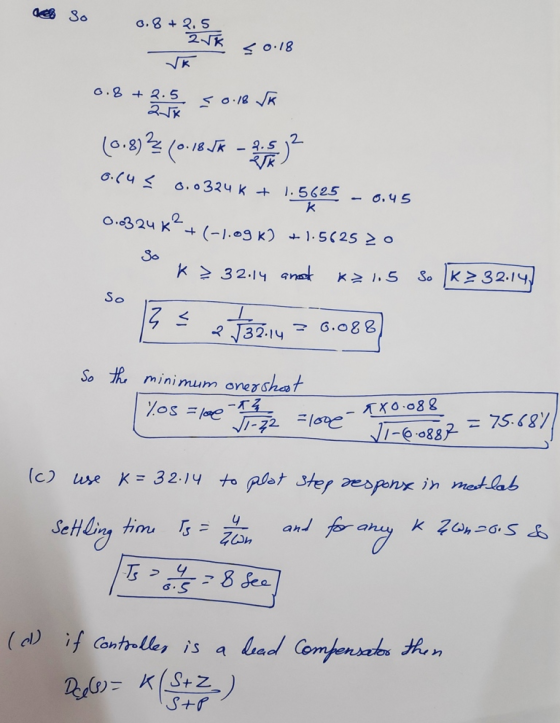
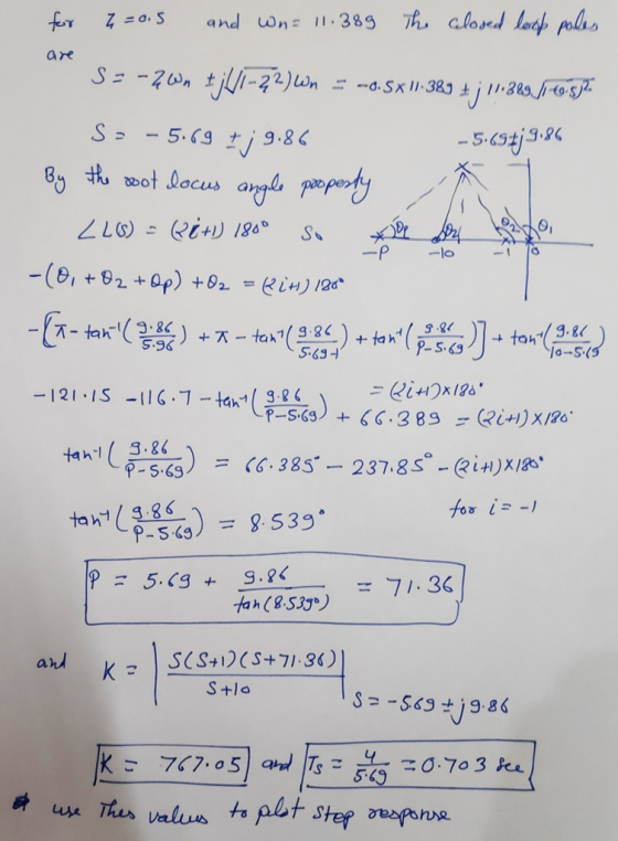
3. Consider the tilt control block diagram shown below R(s) DesiredG(s) 12 s(s+10)(s+70) Y(s) Til...
 3. Consider the tilt control block diagram shown below R(s) DesiredG(s) 12 s(s+10)(s+70) Y(s) Tilt tilt Design specifications require an overshoot of less than 5% and a settling time of less than 0.6 seconds. (a) Use MATLAB to sketch the root locus (rlocus command) with a proportional controller and use the root locus to determine a value for K (if any) that will satisfy the design requirements (b) Design a lead compensator Ge(s) to satisfy the design specifications. You can...
 Please solve part b and c and d !!
Consider the closed loop system shown in Figure 4. The root locus of that system is shown in Figure 5 (s+40s+8) R(s) Y(s) Figure 4 System block diagram of Problem 4 a) On the root locus plot, sketch the region of possible roots of the dominant closed-loop poles such that the system response to a unit step has the following time domain specifications. [5] i. Damping ratio, 20.76 ii. Natural frequency,....
Please solve part b and c and d !!
Consider the closed loop system shown in Figure 4. The root locus of that system is shown in Figure 5 (s+40s+8) R(s) Y(s) Figure 4 System block diagram of Problem 4 a) On the root locus plot, sketch the region of possible roots of the dominant closed-loop poles such that the system response to a unit step has the following time domain specifications. [5] i. Damping ratio, 20.76 ii. Natural frequency,....
 Wis) R(s u(s) 14 Gl(s) H(s) Given a system as in the diagram above, where K is an adjustable parameter pl(s) Dal(sKp+ g) Assuming W-0, find the transfer function Y(s)/R(s) h) Assuming R-0, find the transfer function Y(s)/W(s) i) What is the type of the system (with respect to steady-state error)? j) What is the steady-state error when rt)u(t) (unit-step) and w(t)-0 k) What is the s.s. error when r(t) t u(t) and w(t)-0 ) Assume r(t)-0, what is the...
 only b and c please
1 Consider the system whose transfer function is given by: G(S) == (2s +1)(s+3) unction is given by: G(s) - (a) Use the root-locus design methodology to design a lead compensator that will provide a closed-loop damping 5 =0.4 and a natural frequency on =9 rad/sec. The general transfer function for lead compensation is given by D(5)=K (977), p>z, 2=2 (b) Use MATLAB to plot the root locus of the feed-forward transfer function, D(s)*G(s), and...
only b and c please
1 Consider the system whose transfer function is given by: G(S) == (2s +1)(s+3) unction is given by: G(s) - (a) Use the root-locus design methodology to design a lead compensator that will provide a closed-loop damping 5 =0.4 and a natural frequency on =9 rad/sec. The general transfer function for lead compensation is given by D(5)=K (977), p>z, 2=2 (b) Use MATLAB to plot the root locus of the feed-forward transfer function, D(s)*G(s), and...
 A system having an open loop transfer function of G(S) = K10/(S+2)(3+1) has a root locus plot as shown below. The location of the roots for a system gain of K= 0.248 is show on the plot. At this location the system has a damping factor of 0.708 and a settling time of 4/1.5 = 2.67 seconds. A lead compensator is to be used to improve the transient response. (Note that nothing is plotted on the graph except for that...
 Consider the automobile cruise-control system shown below: Engine ActuatorCarburetor 0.833 and load 40 3s +1 Compensator R(s)E(s) Ge(s) s +1 -t e(t) Sensor 0.03 1) Derive the closed-loop transfer function of V(s)/R(s) when Gc(s)-1 2) Derive the closed-loop transfer function of E(s)/R(s) when Ge(s)-1 3) Plot the time history of the error e(t) of the closed-loop system when r(t) is a unit step input. 4) Plot the root-loci of the uncompensated system (when Gc(s)-1). Mark the closed-loop complex poles on...
 QI: For the following closed loop system below: RCS — -*H 00 For each of the following open loop transfer function Ls): D) L(S) 842)(5) I L ) - +1 (5+1)(5+5)(5+) III) L(S) - 3421(+3) a) Draw the root locus and find the range of k for which the closed-loop system is stable. b) Find the value of k so that the system is marginally stable, and for that value, find the oscillation frequency of the time response. c) Find...
 02: For the following closed loop system below: R(s) or L(s) = (s B's ey draw the root locus stable a) and find the range ofk for which the closed loop system, s (s-B)(S-C) b) for Ls) -GrsmisrG draw the root locus and find the range of k for which the closed loop system is (s+A)(s+B)(s+C) stable. c) For (a) and (b), find.: 1 the value of K so that the system is marginally stable, and for that value, find...
 1. Using the MATLAB rltool command (or rlocus and rlocfind), plot the K > 0 root locus for What is the value of the largest damping ra- 2+2s+1 s(s120)7,7 -2,12). 1 + KL(s) = 0, where L(s) = tio associated with the pair of complex poles? At which value of K is it achieved? Turn in a printout of your plot showing the location of the poles on the damping ratio line that you found. 2. Suppose the unity feedback...
 Determine: 1. The transfer function C(s)/R(s). Also find the
closed-loop poles of the system. 2. The values of the undamped
natural frequency ωN and damping ratio ξ of the closed-loop poles.
3. The expressions of the rise time, the peak time, the maximum
overshoot, and the 2% settling time due to a unit-step reference
signal.
For the open-loop process with negative feedback R(S) Gp(S) C(s) H(s) 103 Go(s) = 1 , Gp(s)- s(s + 4) Determine: 1. The transfer function...
Determine: 1. The transfer function C(s)/R(s). Also find the
closed-loop poles of the system. 2. The values of the undamped
natural frequency ωN and damping ratio ξ of the closed-loop poles.
3. The expressions of the rise time, the peak time, the maximum
overshoot, and the 2% settling time due to a unit-step reference
signal.
For the open-loop process with negative feedback R(S) Gp(S) C(s) H(s) 103 Go(s) = 1 , Gp(s)- s(s + 4) Determine: 1. The transfer function...
 3. Consider the tilt control block diagram shown below R(s) DesiredG(s) 12 s(s+10)(s+70) Y(s) Tilt tilt Design specifications require an overshoot of less than 5% and a settling time of less than 0.6 seconds. (a) Use MATLAB to sketch the root locus (rlocus command) with a proportional controller and use the root locus to determine a value for K (if any) that will satisfy the design requirements (b) Design a lead compensator Ge(s) to satisfy the design specifications. You can...
Most questions answered within 3 hours.
-
Where is the error in this code sequence?
String s1 = "Hello";
String s2 = "ello";...
asked 10 months ago -
Financial data for Joel de Paris, Inc., for last year
follow:
Joel de Paris, Inc.
Balance...
asked 10 months ago -
Consider this reaction:
Al2(SO4)3 (aq)+ BaCl3
(aq) Al2Cl6 (aq)- +
3BaSO4(s) . What is the...
asked 10 months ago -
Suppose that Savneet is considering increasing her
recent random sample from 20 car rentals to 40...
asked 10 months ago -
Trucks arrive at an unloading terminal at an average rate of 120
per hour.
Trucks arrive...
asked 10 months ago -
Why are methanol and ethanol completely soluble in water while
octanol is not very little soluble....
asked 10 months ago -
A facilities manager at a university reads in a research report
that the mean amount of...
asked 10 months ago -
When the CuSO4 is rehydrated by adding water to the anhydrous
compound, is this an endothermic...
asked 10 months ago -
A ray of sunlight is passing from diamond into crown glass; the
angle of incidence is...
asked 10 months ago -
A block of mass 0.249 kg is placed on top of a light, vertical
spring of...
asked 10 months ago -
how do the kidneys compensate in the presences of acidosis
a) trigger hyperventilate
b) reserve acid...
asked 10 months ago -
Question 501 pts
The rental rate of capital to the firm increases. Which of the
following...
asked 10 months ago