
Homework Answers

Add Answer to:
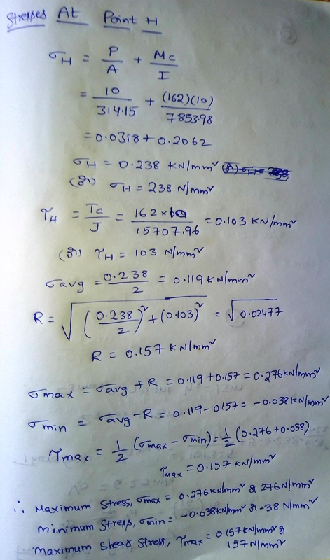
Question 4 Two forces are applied at points A and B of the solid cast-iron bracket shown. Knowing that the bracket has a diameter of 20mm, determine the stresses at point H 20 mm IH 10 kN A 80mm 60 m...
8.42A 13-kN force is applied as shown to the 60-mm-diameter cast-iron post ABD. At point H, determine (a) the principal stresses and principal planes, (b) the maximum shearing stress 13 kN 300 mm 100...
 8.42A 13-kN force is applied as shown to the 60-mm-diameter cast-iron post ABD. At point H, determine (a) the principal stresses and principal planes, (b) the maximum shearing stress 13 kN 300 mm 100 mm 125 mm 150 mm Fig. P8.42
8.42A 13-kN force is applied as shown to the 60-mm-diameter cast-iron post ABD. At point H, determine (a) the principal stresses and principal planes, (b) the maximum shearing stress 13 kN 300 mm 100 mm 125 mm 150 mm...
8.42A 13-kN force is applied as shown to the 60-mm-diameter cast-iron post ABD. At point H, determine (a) the principal stresses and principal planes, (b) the maximum shearing stress 13 kN 300 mm 100 mm 125 mm 150 mm Fig. P8.42
8.42A 13-kN force is applied as shown to the 60-mm-diameter cast-iron post ABD. At point H, determine (a) the principal stresses and principal planes, (b) the maximum shearing stress 13 kN 300 mm 100 mm 125 mm 150 mm...
A 17.5 kN force is applied at Point D of the cast iron post shown. Knowing...
 A 17.5 kN force is applied at Point D of the cast iron post
shown. Knowing that the post has a diameter of 60 mm, using Mohr’s
circle determine the principal stresses and the maximum shearing
stress at Point K
A 17.5 kN force is applied at Point D of the cast iron post shown. Knowing that the post has a diameter of 60 mm, using Mohr's circle determine the principal stresses and the maximum shearing stress at Point K....
A 17.5 kN force is applied at Point D of the cast iron post
shown. Knowing that the post has a diameter of 60 mm, using Mohr’s
circle determine the principal stresses and the maximum shearing
stress at Point K
A 17.5 kN force is applied at Point D of the cast iron post shown. Knowing that the post has a diameter of 60 mm, using Mohr's circle determine the principal stresses and the maximum shearing stress at Point K....
Three forces are applied to the machine component ABD as shown. Knowing that the cross section...
 Three forces are applied to the machine component ABD as shown. Knowing that the cross section containing point H is a 20 x 40- mm rectangle, determine the principal stresses and the maximum shearing stress at point H. Take force Q 3.5 kN. (Round the final answers to two decimal places.) y50 mm 150 mm 0.5 kN 40 mm В 20 mm Q 160 mm 2.5 kN The principal stresses at point Hare as follows: |MPа Оa МPа Оb- The...
2) Two forces P- 18 kN and F 15 kN are applied to the shaft with a diameter of D - 40 mm, as shown. A torque T= 750 N·m is also applied on the free end of the shaft. Determine the location and magnit...
 2) Two forces P- 18 kN and F 15 kN are applied to the shaft with a diameter of D - 40 mm, as shown. A torque T= 750 N·m is also applied on the free end of the shaft. Determine the location and magnitudes of maximum normal and shear stresses developed in the shaft. For full credit, show your work (40 points). T IP
2) Two forces P- 18 kN and F 15 kN are applied to the shaft...
2) Two forces P- 18 kN and F 15 kN are applied to the shaft with a diameter of D - 40 mm, as shown. A torque T= 750 N·m is also applied on the free end of the shaft. Determine the location and magnitudes of maximum normal and shear stresses developed in the shaft. For full credit, show your work (40 points). T IP
2) Two forces P- 18 kN and F 15 kN are applied to the shaft...
Two forces 3 kN and 2.5 kN are applied to the machine component ABD as shown...
 Two forces 3 kN and 2.5 kN are applied to the machine component ABD as shown in Figure 3. Given that the cross section containing the point H is a rectangle of dimensions 20mm x 10mm, determine the following a. Draw the free body diagram at H, and indicate the reaction forces/moments. b. Indicate the state of stress at Point H and the components of stress in the proper directions on a stress block or stress element (as indicated in...
00 Several forces are applied to the pipe assembly shown. Knowing that Q = 230 lb...
 00 Several forces are applied to the pipe assembly shown. Knowing that Q = 230 lb and that the pipe has inner and outer diameters equal to 1.61 in. and 1.90 in., respectively, determine the normal and shearing stresses at point Hand point K. (Round the final answers to decimal places.) 10 points eBook 150 lb Hint 10 in Print 150 lb References 6 in 50 lb The normal stress at point His The shearing stress at point His The...
P2. Two solid steel shafts, each of 30-mm diameter, are connected by the gears shown. Knowing...
 P2. Two solid steel shafts, each of 30-mm diameter, are connected by the gears shown. Knowing that G- 77.2 GPa, determine the angle through which end A rotates when a torque of magnitude T= 200 N.m is applied at A. 0.2 m 30 mm 0.4 m 0.2m 60 mm 0.1m 90 mm 30 mm 0.5 m
Question 3: Two vertical forces are applied to a beam of the cross-section shown with a...
 Question 3: Two vertical forces are applied to a beam of the cross-section shown with a uniform thickness of 10 mm. Determine the maximum tensile and compressive stresses at point G located 0.5 m from point A of the beam. Follow the steps below. 60 kN 60 KN Beam Cross-Section 120 mm A Bc 200 mm 1.5m - 1m 1m Step 1-FBD, SFD and BMD diagrams for the beam. Step 2 - Magnitude of moment at point G (located at...
PROBLEM # 2 (50 points) A riveted structural connection supports a load P-10 kN, as shown...
 PROBLEM # 2 (50 points) A riveted structural connection supports a load P-10 kN, as shown in the figure below. What is the value of the force on the most heavily loaded rivet in the bracket? Determine the value of the bearing stress if the plate is 15 mm thick. The line of action of the applied load passes through point D. -5 at 60 = 300 mm 150 mm Bracket 20 mm rivets Gusset plate
a A horizontal bracket ABC consists of two perpendicular arms AB and BC as shown in...
 a A horizontal bracket ABC consists of two perpendicular arms AB and BC as shown in the figure. Amm AB has a solid circular cross section with diameter equal to 60 mm. At point C a load P = 2.02 EN acts vertically and a load Pa = 3.07 kN acts horizontally and parallel to am AB. For point p, (a) sketch the stress element, (3 marks) 6) calculate the principal planes and the principal stresses and sketch the orientation...
 8.42A 13-kN force is applied as shown to the 60-mm-diameter cast-iron post ABD. At point H, determine (a) the principal stresses and principal planes, (b) the maximum shearing stress 13 kN 300 mm 100 mm 125 mm 150 mm Fig. P8.42
8.42A 13-kN force is applied as shown to the 60-mm-diameter cast-iron post ABD. At point H, determine (a) the principal stresses and principal planes, (b) the maximum shearing stress 13 kN 300 mm 100 mm 125 mm 150 mm...
8.42A 13-kN force is applied as shown to the 60-mm-diameter cast-iron post ABD. At point H, determine (a) the principal stresses and principal planes, (b) the maximum shearing stress 13 kN 300 mm 100 mm 125 mm 150 mm Fig. P8.42
8.42A 13-kN force is applied as shown to the 60-mm-diameter cast-iron post ABD. At point H, determine (a) the principal stresses and principal planes, (b) the maximum shearing stress 13 kN 300 mm 100 mm 125 mm 150 mm...
 A 17.5 kN force is applied at Point D of the cast iron post
shown. Knowing that the post has a diameter of 60 mm, using Mohr’s
circle determine the principal stresses and the maximum shearing
stress at Point K
A 17.5 kN force is applied at Point D of the cast iron post shown. Knowing that the post has a diameter of 60 mm, using Mohr's circle determine the principal stresses and the maximum shearing stress at Point K....
A 17.5 kN force is applied at Point D of the cast iron post
shown. Knowing that the post has a diameter of 60 mm, using Mohr’s
circle determine the principal stresses and the maximum shearing
stress at Point K
A 17.5 kN force is applied at Point D of the cast iron post shown. Knowing that the post has a diameter of 60 mm, using Mohr's circle determine the principal stresses and the maximum shearing stress at Point K....
 Three forces are applied to the machine component ABD as shown. Knowing that the cross section containing point H is a 20 x 40- mm rectangle, determine the principal stresses and the maximum shearing stress at point H. Take force Q 3.5 kN. (Round the final answers to two decimal places.) y50 mm 150 mm 0.5 kN 40 mm В 20 mm Q 160 mm 2.5 kN The principal stresses at point Hare as follows: |MPа Оa МPа Оb- The...
 2) Two forces P- 18 kN and F 15 kN are applied to the shaft with a diameter of D - 40 mm, as shown. A torque T= 750 N·m is also applied on the free end of the shaft. Determine the location and magnitudes of maximum normal and shear stresses developed in the shaft. For full credit, show your work (40 points). T IP
2) Two forces P- 18 kN and F 15 kN are applied to the shaft...
2) Two forces P- 18 kN and F 15 kN are applied to the shaft with a diameter of D - 40 mm, as shown. A torque T= 750 N·m is also applied on the free end of the shaft. Determine the location and magnitudes of maximum normal and shear stresses developed in the shaft. For full credit, show your work (40 points). T IP
2) Two forces P- 18 kN and F 15 kN are applied to the shaft...
 Two forces 3 kN and 2.5 kN are applied to the machine component ABD as shown in Figure 3. Given that the cross section containing the point H is a rectangle of dimensions 20mm x 10mm, determine the following a. Draw the free body diagram at H, and indicate the reaction forces/moments. b. Indicate the state of stress at Point H and the components of stress in the proper directions on a stress block or stress element (as indicated in...
 00 Several forces are applied to the pipe assembly shown. Knowing that Q = 230 lb and that the pipe has inner and outer diameters equal to 1.61 in. and 1.90 in., respectively, determine the normal and shearing stresses at point Hand point K. (Round the final answers to decimal places.) 10 points eBook 150 lb Hint 10 in Print 150 lb References 6 in 50 lb The normal stress at point His The shearing stress at point His The...
 P2. Two solid steel shafts, each of 30-mm diameter, are connected by the gears shown. Knowing that G- 77.2 GPa, determine the angle through which end A rotates when a torque of magnitude T= 200 N.m is applied at A. 0.2 m 30 mm 0.4 m 0.2m 60 mm 0.1m 90 mm 30 mm 0.5 m
 Question 3: Two vertical forces are applied to a beam of the cross-section shown with a uniform thickness of 10 mm. Determine the maximum tensile and compressive stresses at point G located 0.5 m from point A of the beam. Follow the steps below. 60 kN 60 KN Beam Cross-Section 120 mm A Bc 200 mm 1.5m - 1m 1m Step 1-FBD, SFD and BMD diagrams for the beam. Step 2 - Magnitude of moment at point G (located at...
 PROBLEM # 2 (50 points) A riveted structural connection supports a load P-10 kN, as shown in the figure below. What is the value of the force on the most heavily loaded rivet in the bracket? Determine the value of the bearing stress if the plate is 15 mm thick. The line of action of the applied load passes through point D. -5 at 60 = 300 mm 150 mm Bracket 20 mm rivets Gusset plate
 a A horizontal bracket ABC consists of two perpendicular arms AB and BC as shown in the figure. Amm AB has a solid circular cross section with diameter equal to 60 mm. At point C a load P = 2.02 EN acts vertically and a load Pa = 3.07 kN acts horizontally and parallel to am AB. For point p, (a) sketch the stress element, (3 marks) 6) calculate the principal planes and the principal stresses and sketch the orientation...
Most questions answered within 3 hours.
-
Where is the error in this code sequence?
String s1 = "Hello";
String s2 = "ello";...
asked 10 months ago -
Financial data for Joel de Paris, Inc., for last year
follow:
Joel de Paris, Inc.
Balance...
asked 10 months ago -
Consider this reaction:
Al2(SO4)3 (aq)+ BaCl3
(aq) Al2Cl6 (aq)- +
3BaSO4(s) . What is the...
asked 10 months ago -
Suppose that Savneet is considering increasing her
recent random sample from 20 car rentals to 40...
asked 10 months ago -
Trucks arrive at an unloading terminal at an average rate of 120
per hour.
Trucks arrive...
asked 10 months ago -
Why are methanol and ethanol completely soluble in water while
octanol is not very little soluble....
asked 10 months ago -
A facilities manager at a university reads in a research report
that the mean amount of...
asked 10 months ago -
When the CuSO4 is rehydrated by adding water to the anhydrous
compound, is this an endothermic...
asked 10 months ago -
A ray of sunlight is passing from diamond into crown glass; the
angle of incidence is...
asked 10 months ago -
A block of mass 0.249 kg is placed on top of a light, vertical
spring of...
asked 10 months ago -
how do the kidneys compensate in the presences of acidosis
a) trigger hyperventilate
b) reserve acid...
asked 10 months ago -
Question 501 pts
The rental rate of capital to the firm increases. Which of the
following...
asked 10 months ago