design a 4 bit comparator that compares two numbers of 4 bits. the output should be < > or =. however you're only limited to using multiplexers or full adders. any help on how to draw this w...
design a 4 bit comparator that compares two numbers of 4 bits. the output should be < > or =. however you're only limited to using multiplexers or full adders. any help on how to draw this will be appreciated
Homework Answers
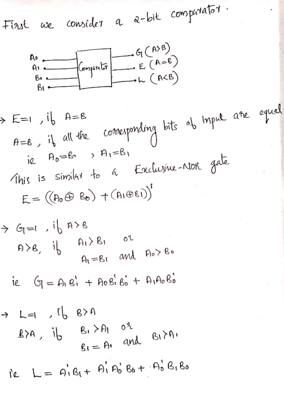
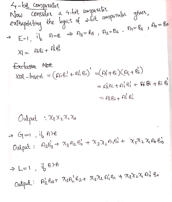
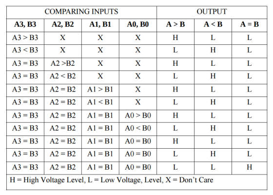
The truth table of the 4bit comparator is given below
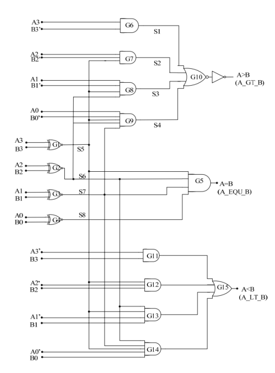
 In
order to implement the above circuit with fewer gates, we modify
the circuit that is shown in the following figure
In
order to implement the above circuit with fewer gates, we modify
the circuit that is shown in the following figure
In order to reduce the area, we can still decrease the number of
gates. The logic of A<B can be decided by A>B and A=B, so we
can simplify the above circuit as below. 2-input NOR is used here
to realize the function of A<B.The area of 2-input NOR is much
less than that of G11~G15. On the other hand, fewer gates means
fewer power, so this modification can greatly reduce the power
dissipation. Therefore, the logic optimization is
completed.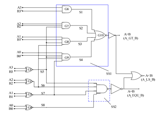
Add Answer to:
design a 4 bit comparator that compares two numbers of 4 bits. the output should be < > or =. however you're only limited to using multiplexers or full adders. any help on how to draw this w...
design a 4 bit comparator that compares two numbers of 4 bits. the output should be...
design a 4 bit comparator that compares two numbers of 4 bits. the output should be < > or =. however you're only limited to using multiplexers or full adders. any help on how to draw this will be appreciated
#5 Design a magnitude comparator that compares two 2-bit numbers, A and B. The system has...
 #5 Design a magnitude comparator that compares two 2-bit numbers, A and B. The system has three outputs that indicate whether A>B, A=B, or A <B. Draw your design with only XNOR, AND, and OR gates. 15
8/8pts Question 1 Using block diagram of 1-bit full adders create a 3-bit parallel adder (show...
 8/8pts Question 1 Using block diagram of 1-bit full adders create a 3-bit parallel adder (show all the connections between the adders and proper outputs Logic Q1jpg 4/9 pts Question 2 Consider your design, if the inputs to be added were 100, and 111, what will be the resulting sum output (Express the resulting sum in binary and base 8 using the least number of bits)? What will be the carry output (Express it only in binary using the least...
For number 2 you can use exclusive-OR gates, but do not use multiplexers. 1. Design a...
 For number 2 you can use
exclusive-OR gates, but do not use multiplexers.
1. Design a 4-bit adder/subtractor using only full adders and EXCLUSIVE- OR gates. Do not use any multiplexers. 2. Design a combinational circuit using a minimum number of Full adders, and logic gates which will perform A plus B or minus B (A and B are signed numbers), depending on a mode select input, M. If M=0, addition is carried out; if M1, subtraction is carried out....
For number 2 you can use
exclusive-OR gates, but do not use multiplexers.
1. Design a 4-bit adder/subtractor using only full adders and EXCLUSIVE- OR gates. Do not use any multiplexers. 2. Design a combinational circuit using a minimum number of Full adders, and logic gates which will perform A plus B or minus B (A and B are signed numbers), depending on a mode select input, M. If M=0, addition is carried out; if M1, subtraction is carried out....
Using building blocks such as binary adders, comparators, multiplexers, decoders, encoders, and arbiters as well as logic gates, design an 8x2 popularity circuit – a circuit that accepts eight two-bit...
Using building blocks such as binary adders, comparators, multiplexers, decoders, encoders, and arbiters as well as logic gates, design an 8x2 popularity circuit – a circuit that accepts eight two-bit numbers and outputs the number of times each of the four numbers appears on the input.
A comparator circuit has two 2-bit inputs, A(0,1) and B(0,1) [4 total inputs], and three 1-bit...
A comparator circuit has two 2-bit inputs, A(0,1) and B(0,1) [4 total inputs], and three 1-bit outputs, G (A greater than B), E (equal), and L (A less than B) (hint: Compare two bits against two bits, for example, if inputs are 0010, then B is greater than A). Write the logic equation for each output, and draw the logic diagram for each output using 8 to 1 Multiplexers (3).
Design a combinational circuit which compares two 4-bit unsigned numbers A and B. The circuit should...
Design a combinational circuit which compares two 4-bit unsigned numbers A and B. The circuit should have one output X such that X = 1 whenever A>B and X = 0 whenever A?B. You may use any MSI modules as well as any other gates.
design and build a 4 bit binary multiplier that multiplies two 4 bit unsigned positive numbers...
design and build a 4 bit binary multiplier that multiplies two 4 bit unsigned positive numbers to generate a 8 bit unsigned positive number. using full adders. do not use 4 bit multiplier chip. use truth table, karnaugh map and simplified output expression of the circuit.
Design a combinational circuit that compares two 4-bit unsigned numbers A and B
Design a combinational circuit that compares two 4-bit unsigned numbers A and B to see whether B is greater than 2A. The circuit has one output X, so that:X = 1 if 2A < B, andX = 0 if 2A >= B.Please de descriptive and detailed in drawing.The book we are using in class is this: http://www.cramster.com/logic-and-computer-design-fundamentals-4th-solutions-3631 and we are on chapter 4.
Design a combinational circuit that compares two 4-bit unsigned numbers A and B to see whether...
Design a combinational circuit that compares two 4-bit unsigned numbers A and B to see whether A is greater than B. The circuit has one output X, so that X = 0 if A ≤ B and X = 1 if A > B.
 #5 Design a magnitude comparator that compares two 2-bit numbers, A and B. The system has three outputs that indicate whether A>B, A=B, or A <B. Draw your design with only XNOR, AND, and OR gates. 15
 8/8pts Question 1 Using block diagram of 1-bit full adders create a 3-bit parallel adder (show all the connections between the adders and proper outputs Logic Q1jpg 4/9 pts Question 2 Consider your design, if the inputs to be added were 100, and 111, what will be the resulting sum output (Express the resulting sum in binary and base 8 using the least number of bits)? What will be the carry output (Express it only in binary using the least...
 For number 2 you can use
exclusive-OR gates, but do not use multiplexers.
1. Design a 4-bit adder/subtractor using only full adders and EXCLUSIVE- OR gates. Do not use any multiplexers. 2. Design a combinational circuit using a minimum number of Full adders, and logic gates which will perform A plus B or minus B (A and B are signed numbers), depending on a mode select input, M. If M=0, addition is carried out; if M1, subtraction is carried out....
For number 2 you can use
exclusive-OR gates, but do not use multiplexers.
1. Design a 4-bit adder/subtractor using only full adders and EXCLUSIVE- OR gates. Do not use any multiplexers. 2. Design a combinational circuit using a minimum number of Full adders, and logic gates which will perform A plus B or minus B (A and B are signed numbers), depending on a mode select input, M. If M=0, addition is carried out; if M1, subtraction is carried out....
Most questions answered within 3 hours.
-
Where is the error in this code sequence?
String s1 = "Hello";
String s2 = "ello";...
asked 11 months ago -
Financial data for Joel de Paris, Inc., for last year
follow:
Joel de Paris, Inc.
Balance...
asked 11 months ago -
Consider this reaction:
Al2(SO4)3 (aq)+ BaCl3
(aq) Al2Cl6 (aq)- +
3BaSO4(s) . What is the...
asked 11 months ago -
Suppose that Savneet is considering increasing her
recent random sample from 20 car rentals to 40...
asked 11 months ago -
Trucks arrive at an unloading terminal at an average rate of 120
per hour.
Trucks arrive...
asked 11 months ago -
Why are methanol and ethanol completely soluble in water while
octanol is not very little soluble....
asked 11 months ago -
A facilities manager at a university reads in a research report
that the mean amount of...
asked 11 months ago -
When the CuSO4 is rehydrated by adding water to the anhydrous
compound, is this an endothermic...
asked 11 months ago -
A ray of sunlight is passing from diamond into crown glass; the
angle of incidence is...
asked 11 months ago -
A block of mass 0.249 kg is placed on top of a light, vertical
spring of...
asked 11 months ago -
how do the kidneys compensate in the presences of acidosis
a) trigger hyperventilate
b) reserve acid...
asked 11 months ago -
Question 501 pts
The rental rate of capital to the firm increases. Which of the
following...
asked 11 months ago