
Homework Answers
Add Answer to:
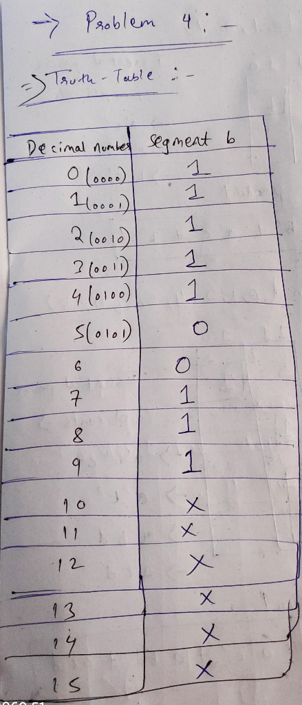
Problem 4.0 (20 Points) Design the segment 'b' of the BCD to 7 segment decoder driver of the common cathode seven segment display. Your design should include the following: Hint th e inval...
Task 3 BCD-to-7-Segment Conversion Derive the truth table for the BCD-to-seven-segment code decoder (a truth table...
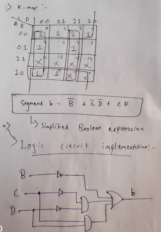
 Task 3 BCD-to-7-Segment Conversion Derive the truth table for the BCD-to-seven-segment code decoder (a truth table with 4 inputs and 7 outputs, where 6 out of 16 input combinations are invalid). Decide on how to handle outputs for illegal input com- binations and describe your choice in your discussion Task 4 Use the WinLogiLab WinBoolean utility K-Map tool to obtain a minimal all-NAND realization for the BCD-to-seven-segment decoder Task 5 Use the WinLogiLab DigitalSim utility to simulate the logic functionality...
You will build a seven-segment display decoder, shown in Figure 3. The circuit has four input...
You will build a seven-segment display decoder, shown in Figure 3. The circuit has four input bits, D3:0 (representing a hexadecimal number between 0 and F), and produces seven output bits, Sa:g, that drive the seven segments to display the number. The 7-segment display we will use in this lab is a common cathode type, a segment of the display turns on when it is 1. The other type of 7-segment display is common anode, for which a segment turns...
A seven segment decoder is a digital circuit that displays an input value 0 through 9 as a digital output in the 7-segment display. The behavior of this design can be modeled with the schematic diagra...
 A seven segment decoder is a digital circuit that
displays an input value 0 through 9 as a digital output in the
7-segment display. The behavior of this design can be modeled with
the schematic diagram below, where DCBA is the 4-bit input (D is
the most significant bit and A is the least significant bit) and
abcdefg is the 7-segment output.
2. (20 POINTS) A seven segment decoder is a digital circuit that displays an input value 0 through...
A seven segment decoder is a digital circuit that
displays an input value 0 through 9 as a digital output in the
7-segment display. The behavior of this design can be modeled with
the schematic diagram below, where DCBA is the 4-bit input (D is
the most significant bit and A is the least significant bit) and
abcdefg is the 7-segment output.
2. (20 POINTS) A seven segment decoder is a digital circuit that displays an input value 0 through...
 Task 3 BCD-to-7-Segment Conversion Derive the truth table for the BCD-to-seven-segment code decoder (a truth table with 4 inputs and 7 outputs, where 6 out of 16 input combinations are invalid). Decide on how to handle outputs for illegal input com- binations and describe your choice in your discussion Task 4 Use the WinLogiLab WinBoolean utility K-Map tool to obtain a minimal all-NAND realization for the BCD-to-seven-segment decoder Task 5 Use the WinLogiLab DigitalSim utility to simulate the logic functionality...
 A seven segment decoder is a digital circuit that
displays an input value 0 through 9 as a digital output in the
7-segment display. The behavior of this design can be modeled with
the schematic diagram below, where DCBA is the 4-bit input (D is
the most significant bit and A is the least significant bit) and
abcdefg is the 7-segment output.
2. (20 POINTS) A seven segment decoder is a digital circuit that displays an input value 0 through...
A seven segment decoder is a digital circuit that
displays an input value 0 through 9 as a digital output in the
7-segment display. The behavior of this design can be modeled with
the schematic diagram below, where DCBA is the 4-bit input (D is
the most significant bit and A is the least significant bit) and
abcdefg is the 7-segment output.
2. (20 POINTS) A seven segment decoder is a digital circuit that displays an input value 0 through...
Most questions answered within 3 hours.
-
Where is the error in this code sequence?
String s1 = "Hello";
String s2 = "ello";...
asked 10 months ago -
Financial data for Joel de Paris, Inc., for last year
follow:
Joel de Paris, Inc.
Balance...
asked 10 months ago -
Consider this reaction:
Al2(SO4)3 (aq)+ BaCl3
(aq) Al2Cl6 (aq)- +
3BaSO4(s) . What is the...
asked 10 months ago -
Suppose that Savneet is considering increasing her
recent random sample from 20 car rentals to 40...
asked 10 months ago -
Trucks arrive at an unloading terminal at an average rate of 120
per hour.
Trucks arrive...
asked 10 months ago -
Why are methanol and ethanol completely soluble in water while
octanol is not very little soluble....
asked 10 months ago -
A facilities manager at a university reads in a research report
that the mean amount of...
asked 10 months ago -
When the CuSO4 is rehydrated by adding water to the anhydrous
compound, is this an endothermic...
asked 10 months ago -
A ray of sunlight is passing from diamond into crown glass; the
angle of incidence is...
asked 10 months ago -
A block of mass 0.249 kg is placed on top of a light, vertical
spring of...
asked 10 months ago -
how do the kidneys compensate in the presences of acidosis
a) trigger hyperventilate
b) reserve acid...
asked 10 months ago -
Question 501 pts
The rental rate of capital to the firm increases. Which of the
following...
asked 10 months ago