Please answer all the questions with MATLAB and also upload the code. Thanks.
Homework Answers
Add Answer to:
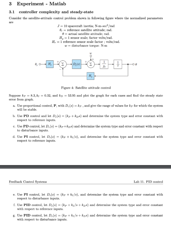
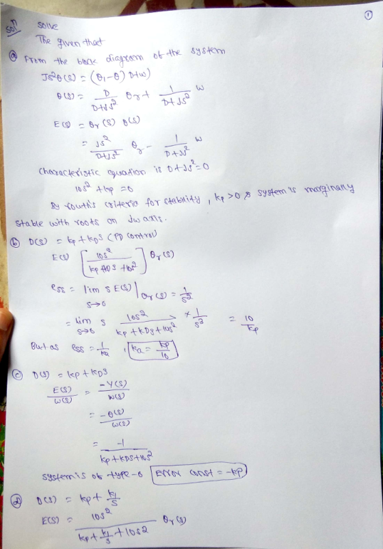
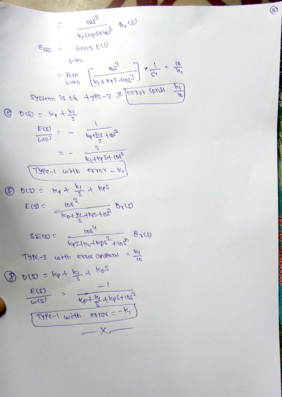
Please answer all the questions with MATLAB and also upload the code. Thanks. 3 Experiment - Matlab controller complexity and steady-state 3.1 Consider the satellite-attitude control problem shown in...
5 Problem 4.41 Consider the second-order plant with transfer function: 1 G(s) = (s1)(5s 1) and...
 5 Problem 4.41 Consider the second-order plant with transfer function: 1 G(s) = (s1)(5s 1) and in a unity feedback structure 1. Determine the system type and error constant with respect to tracking polynomial reference inputs of the system for P (i.e., De = kp), PD (i.e., Dc = kp+kps), and PID (i.e., De=kp +ki/s+ kps) controllers. Let kp = 19,ki 0.5,kp = 4/19. 2. Determine the system type and error constant of the system with respect to disturbance inputs...
Tutorial -On PID control (Control System: Instructor slides and lab) Consider a second order mass...
 part 2 & part 3 please...
Tutorial -On PID control (Control System: Instructor slides and lab) Consider a second order mass-force system to study its behavior under various forms of PID control xtn fon force In Disturbance force: 50) (i.e. wind force) Part I (dealing with the plant/process) 1. What is the model of this system, in other words, write the ODE of the system 2. Derive the transfer function of the above system from Fls) to X(s) 3. What...
part 2 & part 3 please...
Tutorial -On PID control (Control System: Instructor slides and lab) Consider a second order mass-force system to study its behavior under various forms of PID control xtn fon force In Disturbance force: 50) (i.e. wind force) Part I (dealing with the plant/process) 1. What is the model of this system, in other words, write the ODE of the system 2. Derive the transfer function of the above system from Fls) to X(s) 3. What...
please use MATLAB, screenshot the code and the plots. Answer all parts. Laboratory description: The speed...
 please use MATLAB, screenshot the code and the plots. Answer all
parts.
Laboratory description: The speed control of a high-speed train is represented by the system shown in Figure 1. The transfer function of the train dynamics is as follows. G(s) = 2 + 10s + 20 Laboratory assignment: Part A. For the open-loop system described by the following block diagram, assume that the input r(t) is a unit step. (1) Compute the steady-state system output Yss. (2) Find the...
please use MATLAB, screenshot the code and the plots. Answer all
parts.
Laboratory description: The speed control of a high-speed train is represented by the system shown in Figure 1. The transfer function of the train dynamics is as follows. G(s) = 2 + 10s + 20 Laboratory assignment: Part A. For the open-loop system described by the following block diagram, assume that the input r(t) is a unit step. (1) Compute the steady-state system output Yss. (2) Find the...
Problem 4 (25%) Consider the attitude control system of a rigid satellite shown in Figure 1.1....
 Problem 4 (25%) Consider the attitude control system of a rigid satellite shown in Figure 1.1. Fig. 1.1 Satellite tracking control system In this problem we will only consider the control of the angle e (angle of elevation). The dynamic model of the rigid satellite, rotating about an axis perpendicular to the page, can be approximately written as: JÖ = tm - ty - bė where ) is the satellite's moment of inertia, b is the damping coefficient, tm is...
PLEASE DO IN MATLAB Problem 8 (PID feedback control). This problem is about Proportional-Integral-Derivative feedback control...
 PLEASE DO IN MATLAB
Problem 8 (PID feedback control). This problem is about Proportional-Integral-Derivative feedback control systems. The general setup of the system we are going to look at is given below: e(t) u(t) |C(s) y(t) P(s) r(t) Here the various signals are: signal/system r(t) y(t) e(t) P(s) C(s) и(t) meaning desired output signal actual output signal error signal r(t) y(t) Laplace transform of the (unstable) plant controller to be designed control signal Our goal is to design a controller...
PLEASE DO IN MATLAB
Problem 8 (PID feedback control). This problem is about Proportional-Integral-Derivative feedback control systems. The general setup of the system we are going to look at is given below: e(t) u(t) |C(s) y(t) P(s) r(t) Here the various signals are: signal/system r(t) y(t) e(t) P(s) C(s) и(t) meaning desired output signal actual output signal error signal r(t) y(t) Laplace transform of the (unstable) plant controller to be designed control signal Our goal is to design a controller...
control system System Description: The figure 1 and 2 below show, respectively, components and block diagram...
 control system
System Description: The figure 1 and 2 below show, respectively, components and block diagram of a motor and the measurements of velocity (via the tacho unit) and position (via the potentiometer). n represents the gearbox ratio between the rotating shaft and the output shaft. The left-hand side of the diagram represents the controller. A reference set point for the rotating shaft is entered in degrees and this is equivalent voltage. The error is calculated by subtracting the measured...
control system
System Description: The figure 1 and 2 below show, respectively, components and block diagram of a motor and the measurements of velocity (via the tacho unit) and position (via the potentiometer). n represents the gearbox ratio between the rotating shaft and the output shaft. The left-hand side of the diagram represents the controller. A reference set point for the rotating shaft is entered in degrees and this is equivalent voltage. The error is calculated by subtracting the measured...
MATLAB question. Please answer all the questions and also upload the code by MATLAB. Thanks. Down vote if no code provided. For the circuit shown above, at the moment t = 0, the switch is closed, fin...
 MATLAB question. Please answer all the questions and also upload
the code by MATLAB. Thanks. Down vote if no code provided.
For the circuit shown above, at the moment t = 0, the switch is closed, find w(t) for 120, No energy is stored in the capacitor and inductor at moment t-0 1. Write the dynamic model for RLC circuit after t> 0? a. Show all vour work and calculations b. Write down the characteristic equation of the transfer function...
MATLAB question. Please answer all the questions and also upload
the code by MATLAB. Thanks. Down vote if no code provided.
For the circuit shown above, at the moment t = 0, the switch is closed, find w(t) for 120, No energy is stored in the capacitor and inductor at moment t-0 1. Write the dynamic model for RLC circuit after t> 0? a. Show all vour work and calculations b. Write down the characteristic equation of the transfer function...
 5 Problem 4.41 Consider the second-order plant with transfer function: 1 G(s) = (s1)(5s 1) and in a unity feedback structure 1. Determine the system type and error constant with respect to tracking polynomial reference inputs of the system for P (i.e., De = kp), PD (i.e., Dc = kp+kps), and PID (i.e., De=kp +ki/s+ kps) controllers. Let kp = 19,ki 0.5,kp = 4/19. 2. Determine the system type and error constant of the system with respect to disturbance inputs...
 part 2 & part 3 please...
Tutorial -On PID control (Control System: Instructor slides and lab) Consider a second order mass-force system to study its behavior under various forms of PID control xtn fon force In Disturbance force: 50) (i.e. wind force) Part I (dealing with the plant/process) 1. What is the model of this system, in other words, write the ODE of the system 2. Derive the transfer function of the above system from Fls) to X(s) 3. What...
part 2 & part 3 please...
Tutorial -On PID control (Control System: Instructor slides and lab) Consider a second order mass-force system to study its behavior under various forms of PID control xtn fon force In Disturbance force: 50) (i.e. wind force) Part I (dealing with the plant/process) 1. What is the model of this system, in other words, write the ODE of the system 2. Derive the transfer function of the above system from Fls) to X(s) 3. What...
 please use MATLAB, screenshot the code and the plots. Answer all
parts.
Laboratory description: The speed control of a high-speed train is represented by the system shown in Figure 1. The transfer function of the train dynamics is as follows. G(s) = 2 + 10s + 20 Laboratory assignment: Part A. For the open-loop system described by the following block diagram, assume that the input r(t) is a unit step. (1) Compute the steady-state system output Yss. (2) Find the...
please use MATLAB, screenshot the code and the plots. Answer all
parts.
Laboratory description: The speed control of a high-speed train is represented by the system shown in Figure 1. The transfer function of the train dynamics is as follows. G(s) = 2 + 10s + 20 Laboratory assignment: Part A. For the open-loop system described by the following block diagram, assume that the input r(t) is a unit step. (1) Compute the steady-state system output Yss. (2) Find the...
 Problem 4 (25%) Consider the attitude control system of a rigid satellite shown in Figure 1.1. Fig. 1.1 Satellite tracking control system In this problem we will only consider the control of the angle e (angle of elevation). The dynamic model of the rigid satellite, rotating about an axis perpendicular to the page, can be approximately written as: JÖ = tm - ty - bė where ) is the satellite's moment of inertia, b is the damping coefficient, tm is...
 PLEASE DO IN MATLAB
Problem 8 (PID feedback control). This problem is about Proportional-Integral-Derivative feedback control systems. The general setup of the system we are going to look at is given below: e(t) u(t) |C(s) y(t) P(s) r(t) Here the various signals are: signal/system r(t) y(t) e(t) P(s) C(s) и(t) meaning desired output signal actual output signal error signal r(t) y(t) Laplace transform of the (unstable) plant controller to be designed control signal Our goal is to design a controller...
PLEASE DO IN MATLAB
Problem 8 (PID feedback control). This problem is about Proportional-Integral-Derivative feedback control systems. The general setup of the system we are going to look at is given below: e(t) u(t) |C(s) y(t) P(s) r(t) Here the various signals are: signal/system r(t) y(t) e(t) P(s) C(s) и(t) meaning desired output signal actual output signal error signal r(t) y(t) Laplace transform of the (unstable) plant controller to be designed control signal Our goal is to design a controller...
 control system
System Description: The figure 1 and 2 below show, respectively, components and block diagram of a motor and the measurements of velocity (via the tacho unit) and position (via the potentiometer). n represents the gearbox ratio between the rotating shaft and the output shaft. The left-hand side of the diagram represents the controller. A reference set point for the rotating shaft is entered in degrees and this is equivalent voltage. The error is calculated by subtracting the measured...
control system
System Description: The figure 1 and 2 below show, respectively, components and block diagram of a motor and the measurements of velocity (via the tacho unit) and position (via the potentiometer). n represents the gearbox ratio between the rotating shaft and the output shaft. The left-hand side of the diagram represents the controller. A reference set point for the rotating shaft is entered in degrees and this is equivalent voltage. The error is calculated by subtracting the measured...
 MATLAB question. Please answer all the questions and also upload
the code by MATLAB. Thanks. Down vote if no code provided.
For the circuit shown above, at the moment t = 0, the switch is closed, find w(t) for 120, No energy is stored in the capacitor and inductor at moment t-0 1. Write the dynamic model for RLC circuit after t> 0? a. Show all vour work and calculations b. Write down the characteristic equation of the transfer function...
MATLAB question. Please answer all the questions and also upload
the code by MATLAB. Thanks. Down vote if no code provided.
For the circuit shown above, at the moment t = 0, the switch is closed, find w(t) for 120, No energy is stored in the capacitor and inductor at moment t-0 1. Write the dynamic model for RLC circuit after t> 0? a. Show all vour work and calculations b. Write down the characteristic equation of the transfer function...
Most questions answered within 3 hours.
-
Where is the error in this code sequence?
String s1 = "Hello";
String s2 = "ello";...
asked 11 months ago -
Financial data for Joel de Paris, Inc., for last year
follow:
Joel de Paris, Inc.
Balance...
asked 11 months ago -
Consider this reaction:
Al2(SO4)3 (aq)+ BaCl3
(aq) Al2Cl6 (aq)- +
3BaSO4(s) . What is the...
asked 11 months ago -
Suppose that Savneet is considering increasing her
recent random sample from 20 car rentals to 40...
asked 11 months ago -
Trucks arrive at an unloading terminal at an average rate of 120
per hour.
Trucks arrive...
asked 11 months ago -
Why are methanol and ethanol completely soluble in water while
octanol is not very little soluble....
asked 11 months ago -
A facilities manager at a university reads in a research report
that the mean amount of...
asked 11 months ago -
When the CuSO4 is rehydrated by adding water to the anhydrous
compound, is this an endothermic...
asked 11 months ago -
A ray of sunlight is passing from diamond into crown glass; the
angle of incidence is...
asked 11 months ago -
A block of mass 0.249 kg is placed on top of a light, vertical
spring of...
asked 11 months ago -
how do the kidneys compensate in the presences of acidosis
a) trigger hyperventilate
b) reserve acid...
asked 11 months ago -
Question 501 pts
The rental rate of capital to the firm increases. Which of the
following...
asked 11 months ago