
Homework Answers


Add Answer to:
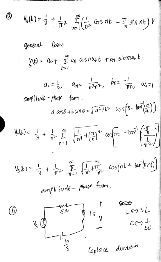
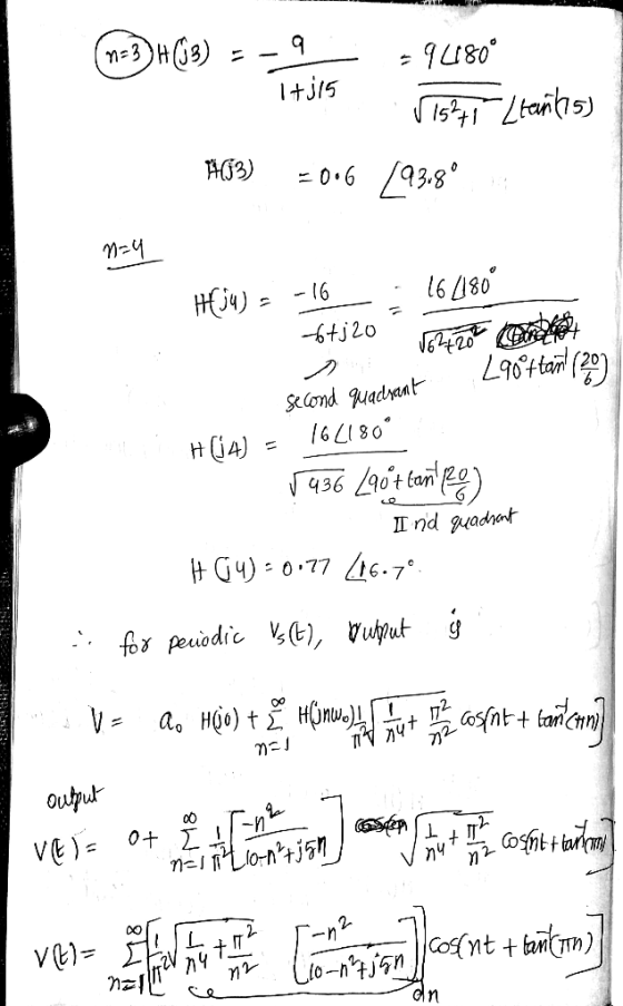
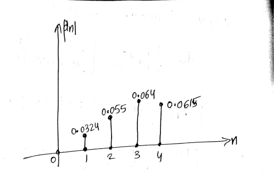
Electrical engineering problem 1251 Problem 2 For the circuit below a) Convert input V.lt) into Amplitude and phase form b) Find the output response V(t) using Fourier series in the circuit shown, dra...
Q#2 (22 points) (a) Find the Fourier series of the function by expanding the function as...
 Q#2 (22 points) (a) Find the Fourier series of the function by expanding the function as an odd periodic function with a period of 10 units, as shown in Figure below. Plot the first, second, third and fourth partial sums of this Fourier series between -5 to +5 (Matlab is preferable). There will be single graph with 4 plots (b) Draw the amplitude versus frequency spectrum for first four non-zero terms of the Fourier series. Note that y(t) for -5<t<...
Problem 04: A voltage source is expressed by the following Fourier series: v(t) = -2 +...
 Problem 04: A voltage source is expressed by the following Fourier series: v(t) = -2 + 5* sin(t) – 5*cos(t) – 3* sin(2*t) + 4*cos(2*t) – sin(3*t) – 6*cos(3*t) + 4*sin(4*t) + 6*cos(4*t). Now, (a) Express v(t) in amplitude-phase form. (b) Draw the amplitude and phase spectra of v(t) (c) Determine the effective value (rms value) of the voltage v(t) (d) If the voltage is applied across an impedance block as shown in the circuit below, determine the average power...
Using parsevals theorem and FT to find y(t) and its power (b) (4 pts) Fourier Series The input signal r(t) and impulse...
 Using parsevals theorem and FT to find y(t) and its power
(b) (4 pts) Fourier Series The input signal r(t) and impulse response h(t) of an LTI system are as follows: z(t) = sin(2t)cos(t)-e131 + 2 and h(t) = sin(21) Use the Fourier Series method to find the output y(t) (c) (4 pts) Parseval's Identity and Theorem. Consider the system in the previous problem. Use Parseval's Identity to compute the power P of the output y(t). Use Parseval's Theorem to...
Using parsevals theorem and FT to find y(t) and its power
(b) (4 pts) Fourier Series The input signal r(t) and impulse response h(t) of an LTI system are as follows: z(t) = sin(2t)cos(t)-e131 + 2 and h(t) = sin(21) Use the Fourier Series method to find the output y(t) (c) (4 pts) Parseval's Identity and Theorem. Consider the system in the previous problem. Use Parseval's Identity to compute the power P of the output y(t). Use Parseval's Theorem to...
PROBLEM III (25 points) The signal v,(t) circuit 2 cos(20rt) cos(10rt) is placed at the input...
 PROBLEM III (25 points) The signal v,(t) circuit 2 cos(20rt) cos(10rt) is placed at the input of a linear and time invariant Ideal #1 low-pass filter with frequency response H(o) al where de 20π. Find the output signal v2(t) using Fourier transform.
4. (15 points - PA.3) Consider the RLC circuit shown below, where the input and output...
 4. (15 points - PA.3) Consider the RLC circuit shown below, where the input and output x(t) and y(t) are the input voltage vi(t) and capacitor voltage vc(t) respectively, and R = 1 K12, C = 0.1 mF, L = 100 H. i(t) + (i) Determine the frequency response of the system H (jw), as well as its magnitude and phase responses. What type of filter does it correspond to? (ii) Sketch its magnitude and phase response in Matlab. You...
2. (14 points) This problem shows an example of using the Fourier transform to analyze communicat...
 2. (14 points) This problem shows an example of using the Fourier transform to analyze communication systems. The system in Figure 4, where (t)-f(t)+sin(wt) and has been proposed for amplitude modulation. f(t) + sin(o) Figure 4: System proposed for amplitude modulation. (a) (7 points) The spectrum of the input f(t) is shown in Figure 1, where 2mB o/100. Sketch and label the spectrum Y(w) of the signal y(t). Hint: You will need to use the frequency convolution property of the...
Problem 24: (18 points) 1. (6 points) Figure 2 shows an RC circuit with input f(t)...
 Problem 24: (18 points) 1. (6 points) Figure 2 shows an RC circuit with input f(t) and output y(t) Function Generator R, v, (r) y1) Figure 2: RC circuit. (a) (1 point) Sketch the circuit in the phasor domain by replacing the capacitor with its impedance represen- (b) (3 points) Using circuit analysis techniques, show that the frequency response function is Specify the DC gain, K, and the time constant, T, in terms of the parameters R, R, and C...
(e) Consider an LTI system with impulse response h(t) = π8ǐnc(2(t-1). i. (5 pts) Find the frequency response H(jw). Hint: Use the FT properties and pairs tables. ii. (5 pts) Find the output y(t) when...
 (e) Consider an LTI system with impulse response h(t) = π8ǐnc(2(t-1). i. (5 pts) Find the frequency response H(jw). Hint: Use the FT properties and pairs tables. ii. (5 pts) Find the output y(t) when the input is (tsin(t) by using the Fourier Transform method. 3. Fourier Transforms: LTI Systems Described by LCCDE (35 pts) (a) Consider a causal (meaning zero initial conditions) LTI system represented by its input-output relationship in the form of a differential equation:-p +3讐+ 2y(t)--r(t). i....
Problem 4: [8 Points] x(t) is a continuous periodic signal that has complex exponential Fourier series coefficients as Do = 1, Dn = 2 (1 + j(-1)") Sketch the magnitude and phase spectral-line...
 Problem 4: [8 Points] x(t) is a continuous periodic signal that has complex exponential Fourier series coefficients as Do = 1, Dn = 2 (1 + j(-1)") Sketch the magnitude and phase spectral-line up to the a) b) Estimate the signal's power from the 1t four h c) Write the math ematical expression for the complex exponential Fourier series expansion form. 12) Solution:
Problem 4: [8 Points] x(t) is a continuous periodic signal that has complex exponential Fourier series coefficients...
Problem 4: [8 Points] x(t) is a continuous periodic signal that has complex exponential Fourier series coefficients as Do = 1, Dn = 2 (1 + j(-1)") Sketch the magnitude and phase spectral-line up to the a) b) Estimate the signal's power from the 1t four h c) Write the math ematical expression for the complex exponential Fourier series expansion form. 12) Solution:
Problem 4: [8 Points] x(t) is a continuous periodic signal that has complex exponential Fourier series coefficients...
1. Consider the single-phase VSI inverter shown below dc VR(t) iz(t) a) If your input voltage Vdc...
 1. Consider the single-phase VSI inverter shown below dc VR(t) iz(t) a) If your input voltage Vdc - 100V2 V and switching frequency is 60 Hz with zero delay angle. Then, sketch the square wave output. Mark the peak values [10 marks] b) Sketch the fundamental output on the top of the above waveform. Mark the peak value По marksl c) The above A VSI is used to create a square wave output with 100v2 V at 60 Hz. This...
 Q#2 (22 points) (a) Find the Fourier series of the function by expanding the function as an odd periodic function with a period of 10 units, as shown in Figure below. Plot the first, second, third and fourth partial sums of this Fourier series between -5 to +5 (Matlab is preferable). There will be single graph with 4 plots (b) Draw the amplitude versus frequency spectrum for first four non-zero terms of the Fourier series. Note that y(t) for -5<t<...
 Problem 04: A voltage source is expressed by the following Fourier series: v(t) = -2 + 5* sin(t) – 5*cos(t) – 3* sin(2*t) + 4*cos(2*t) – sin(3*t) – 6*cos(3*t) + 4*sin(4*t) + 6*cos(4*t). Now, (a) Express v(t) in amplitude-phase form. (b) Draw the amplitude and phase spectra of v(t) (c) Determine the effective value (rms value) of the voltage v(t) (d) If the voltage is applied across an impedance block as shown in the circuit below, determine the average power...
 Using parsevals theorem and FT to find y(t) and its power
(b) (4 pts) Fourier Series The input signal r(t) and impulse response h(t) of an LTI system are as follows: z(t) = sin(2t)cos(t)-e131 + 2 and h(t) = sin(21) Use the Fourier Series method to find the output y(t) (c) (4 pts) Parseval's Identity and Theorem. Consider the system in the previous problem. Use Parseval's Identity to compute the power P of the output y(t). Use Parseval's Theorem to...
Using parsevals theorem and FT to find y(t) and its power
(b) (4 pts) Fourier Series The input signal r(t) and impulse response h(t) of an LTI system are as follows: z(t) = sin(2t)cos(t)-e131 + 2 and h(t) = sin(21) Use the Fourier Series method to find the output y(t) (c) (4 pts) Parseval's Identity and Theorem. Consider the system in the previous problem. Use Parseval's Identity to compute the power P of the output y(t). Use Parseval's Theorem to...
 PROBLEM III (25 points) The signal v,(t) circuit 2 cos(20rt) cos(10rt) is placed at the input of a linear and time invariant Ideal #1 low-pass filter with frequency response H(o) al where de 20π. Find the output signal v2(t) using Fourier transform.
 4. (15 points - PA.3) Consider the RLC circuit shown below, where the input and output x(t) and y(t) are the input voltage vi(t) and capacitor voltage vc(t) respectively, and R = 1 K12, C = 0.1 mF, L = 100 H. i(t) + (i) Determine the frequency response of the system H (jw), as well as its magnitude and phase responses. What type of filter does it correspond to? (ii) Sketch its magnitude and phase response in Matlab. You...
 2. (14 points) This problem shows an example of using the Fourier transform to analyze communication systems. The system in Figure 4, where (t)-f(t)+sin(wt) and has been proposed for amplitude modulation. f(t) + sin(o) Figure 4: System proposed for amplitude modulation. (a) (7 points) The spectrum of the input f(t) is shown in Figure 1, where 2mB o/100. Sketch and label the spectrum Y(w) of the signal y(t). Hint: You will need to use the frequency convolution property of the...
 Problem 24: (18 points) 1. (6 points) Figure 2 shows an RC circuit with input f(t) and output y(t) Function Generator R, v, (r) y1) Figure 2: RC circuit. (a) (1 point) Sketch the circuit in the phasor domain by replacing the capacitor with its impedance represen- (b) (3 points) Using circuit analysis techniques, show that the frequency response function is Specify the DC gain, K, and the time constant, T, in terms of the parameters R, R, and C...
 (e) Consider an LTI system with impulse response h(t) = π8ǐnc(2(t-1). i. (5 pts) Find the frequency response H(jw). Hint: Use the FT properties and pairs tables. ii. (5 pts) Find the output y(t) when the input is (tsin(t) by using the Fourier Transform method. 3. Fourier Transforms: LTI Systems Described by LCCDE (35 pts) (a) Consider a causal (meaning zero initial conditions) LTI system represented by its input-output relationship in the form of a differential equation:-p +3讐+ 2y(t)--r(t). i....
 Problem 4: [8 Points] x(t) is a continuous periodic signal that has complex exponential Fourier series coefficients as Do = 1, Dn = 2 (1 + j(-1)") Sketch the magnitude and phase spectral-line up to the a) b) Estimate the signal's power from the 1t four h c) Write the math ematical expression for the complex exponential Fourier series expansion form. 12) Solution:
Problem 4: [8 Points] x(t) is a continuous periodic signal that has complex exponential Fourier series coefficients...
Problem 4: [8 Points] x(t) is a continuous periodic signal that has complex exponential Fourier series coefficients as Do = 1, Dn = 2 (1 + j(-1)") Sketch the magnitude and phase spectral-line up to the a) b) Estimate the signal's power from the 1t four h c) Write the math ematical expression for the complex exponential Fourier series expansion form. 12) Solution:
Problem 4: [8 Points] x(t) is a continuous periodic signal that has complex exponential Fourier series coefficients...
 1. Consider the single-phase VSI inverter shown below dc VR(t) iz(t) a) If your input voltage Vdc - 100V2 V and switching frequency is 60 Hz with zero delay angle. Then, sketch the square wave output. Mark the peak values [10 marks] b) Sketch the fundamental output on the top of the above waveform. Mark the peak value По marksl c) The above A VSI is used to create a square wave output with 100v2 V at 60 Hz. This...
Most questions answered within 3 hours.
-
Where is the error in this code sequence?
String s1 = "Hello";
String s2 = "ello";...
asked 11 months ago -
Financial data for Joel de Paris, Inc., for last year
follow:
Joel de Paris, Inc.
Balance...
asked 11 months ago -
Consider this reaction:
Al2(SO4)3 (aq)+ BaCl3
(aq) Al2Cl6 (aq)- +
3BaSO4(s) . What is the...
asked 11 months ago -
Suppose that Savneet is considering increasing her
recent random sample from 20 car rentals to 40...
asked 11 months ago -
Trucks arrive at an unloading terminal at an average rate of 120
per hour.
Trucks arrive...
asked 11 months ago -
Why are methanol and ethanol completely soluble in water while
octanol is not very little soluble....
asked 11 months ago -
A facilities manager at a university reads in a research report
that the mean amount of...
asked 11 months ago -
When the CuSO4 is rehydrated by adding water to the anhydrous
compound, is this an endothermic...
asked 11 months ago -
A ray of sunlight is passing from diamond into crown glass; the
angle of incidence is...
asked 11 months ago -
A block of mass 0.249 kg is placed on top of a light, vertical
spring of...
asked 11 months ago -
how do the kidneys compensate in the presences of acidosis
a) trigger hyperventilate
b) reserve acid...
asked 11 months ago -
Question 501 pts
The rental rate of capital to the firm increases. Which of the
following...
asked 11 months ago