ONLY NEED HELP WITH III and IV PLEASE
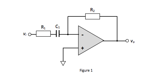
R2 R1 C1 Figure 1
Homework Answers
Add Answer to:
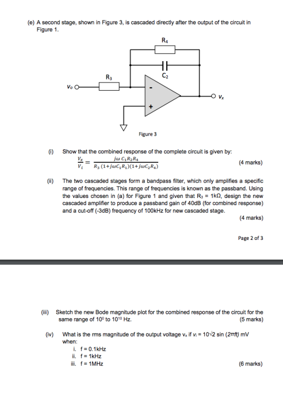
ONLY NEED HELP WITH III and IV PLEASE (e) A second stage, shown in Figure 3, is cascaded directly after the output of the circuit in Figure 1 R4 Figure 3 (i) Show that the combined response of the c...
ONLY NEED HELP WITH C AND D PLEASE! The differentiator circuit shown in Figure 1 uses an op-amp with ideal characteristics C1 Figure 1 (a) Prove that the gain of the circuit is given by the following...
 ONLY NEED HELP WITH C AND D PLEASE!
The differentiator circuit shown in Figure 1 uses an op-amp with ideal characteristics C1 Figure 1 (a) Prove that the gain of the circuit is given by the following expression using first principles for an ideal op-amp (2 marks) Gain = - (1 + juli R 1) (b) If the differentiator frequency (at unity gain) is 100Hz and the high frequency gain is 40dB and R2 is 220kQ, design the rest of...
ONLY NEED HELP WITH C AND D PLEASE!
The differentiator circuit shown in Figure 1 uses an op-amp with ideal characteristics C1 Figure 1 (a) Prove that the gain of the circuit is given by the following expression using first principles for an ideal op-amp (2 marks) Gain = - (1 + juli R 1) (b) If the differentiator frequency (at unity gain) is 100Hz and the high frequency gain is 40dB and R2 is 220kQ, design the rest of...
need help with C and D please The differentiator circuit shown in Figure 1 uses an op-amp with ideal characteristics. R2 R1 C1 Vi O Figure 1 (c) Sketch the Bode magnitude response for this circ...
 need help with C and D please
The differentiator circuit shown in Figure 1 uses an op-amp with ideal characteristics. R2 R1 C1 Vi O Figure 1 (c) Sketch the Bode magnitude response for this circuit for the frequency range of 10° to 108 Hz. (7 marks) (d) Sketch the output waveform of the differentiator and justify your answer, if v is as shown in Figure 2 with a period of: () 100 ms (ii) 10 us (6 marks) 0.11...
need help with C and D please
The differentiator circuit shown in Figure 1 uses an op-amp with ideal characteristics. R2 R1 C1 Vi O Figure 1 (c) Sketch the Bode magnitude response for this circuit for the frequency range of 10° to 108 Hz. (7 marks) (d) Sketch the output waveform of the differentiator and justify your answer, if v is as shown in Figure 2 with a period of: () 100 ms (ii) 10 us (6 marks) 0.11...
 ONLY NEED HELP WITH C AND D PLEASE!
The differentiator circuit shown in Figure 1 uses an op-amp with ideal characteristics C1 Figure 1 (a) Prove that the gain of the circuit is given by the following expression using first principles for an ideal op-amp (2 marks) Gain = - (1 + juli R 1) (b) If the differentiator frequency (at unity gain) is 100Hz and the high frequency gain is 40dB and R2 is 220kQ, design the rest of...
ONLY NEED HELP WITH C AND D PLEASE!
The differentiator circuit shown in Figure 1 uses an op-amp with ideal characteristics C1 Figure 1 (a) Prove that the gain of the circuit is given by the following expression using first principles for an ideal op-amp (2 marks) Gain = - (1 + juli R 1) (b) If the differentiator frequency (at unity gain) is 100Hz and the high frequency gain is 40dB and R2 is 220kQ, design the rest of...
 need help with C and D please
The differentiator circuit shown in Figure 1 uses an op-amp with ideal characteristics. R2 R1 C1 Vi O Figure 1 (c) Sketch the Bode magnitude response for this circuit for the frequency range of 10° to 108 Hz. (7 marks) (d) Sketch the output waveform of the differentiator and justify your answer, if v is as shown in Figure 2 with a period of: () 100 ms (ii) 10 us (6 marks) 0.11...
need help with C and D please
The differentiator circuit shown in Figure 1 uses an op-amp with ideal characteristics. R2 R1 C1 Vi O Figure 1 (c) Sketch the Bode magnitude response for this circuit for the frequency range of 10° to 108 Hz. (7 marks) (d) Sketch the output waveform of the differentiator and justify your answer, if v is as shown in Figure 2 with a period of: () 100 ms (ii) 10 us (6 marks) 0.11...
Most questions answered within 3 hours.
-
Where is the error in this code sequence?
String s1 = "Hello";
String s2 = "ello";...
asked 11 months ago -
Financial data for Joel de Paris, Inc., for last year
follow:
Joel de Paris, Inc.
Balance...
asked 11 months ago -
Consider this reaction:
Al2(SO4)3 (aq)+ BaCl3
(aq) Al2Cl6 (aq)- +
3BaSO4(s) . What is the...
asked 11 months ago -
Suppose that Savneet is considering increasing her
recent random sample from 20 car rentals to 40...
asked 11 months ago -
Trucks arrive at an unloading terminal at an average rate of 120
per hour.
Trucks arrive...
asked 11 months ago -
Why are methanol and ethanol completely soluble in water while
octanol is not very little soluble....
asked 11 months ago -
A facilities manager at a university reads in a research report
that the mean amount of...
asked 11 months ago -
When the CuSO4 is rehydrated by adding water to the anhydrous
compound, is this an endothermic...
asked 11 months ago -
A ray of sunlight is passing from diamond into crown glass; the
angle of incidence is...
asked 11 months ago -
A block of mass 0.249 kg is placed on top of a light, vertical
spring of...
asked 11 months ago -
how do the kidneys compensate in the presences of acidosis
a) trigger hyperventilate
b) reserve acid...
asked 11 months ago -
Question 501 pts
The rental rate of capital to the firm increases. Which of the
following...
asked 11 months ago