
Homework Answers

Add Answer to:
Problem 2 (25 Pts,) Root locus: A proportional only action is controlling a plant with unity feedback. The plant transfer function is: 6 G)+ G+2)(6 +3) a. Draw the poles of G (s) in below figure...
oble2 (25 Pts.) Root Locus: A proportional only action is controlling a plant with unity feedback. The plant ansfer function is: 6 GG)s+ 1)s + 2)s +3) a. Draw the poles of G(s) in below figure b....
 oble2 (25 Pts.) Root Locus: A proportional only action is controlling a plant with unity feedback. The plant ansfer function is: 6 GG)s+ 1)s + 2)s +3) a. Draw the poles of G(s) in below figure b. How many asymptotes does the root locus plot of the above transfer function has? c. What angles do the asymptotes make with the positive real axis in the s plane? d. At what point do the asymptotes intersect on the real axis? e....
Problem 2 For the unity feedback system below in Figure 2 G(s) Figure 2. With (8+2) G(s) = (a) Sk...
 Problem 2 For the unity feedback system below in Figure 2 G(s) Figure 2. With (8+2) G(s) = (a) Sketch the root locus. 1. Draw the finite open-loop poles and zeros. ii. Draw the real-axis root locus iii. Draw the asymptotes and root locus branches. (b) Find the value of gain that will make the system marginally stable. (c) Find the value of gain for which the closed-loop transfer function will have a pole on the real axis at s...
[7] Sketch the root locus for the unity feedback system whose open loop transfer function is K G(s) Draw the root locus...
 [7] Sketch the root locus for the unity feedback system whose open loop transfer function is K G(s) Draw the root locus of the system with the gain K as a variable s(s+4) (s2+4s+20)' Determine asymptotes, centroid,, breakaway point, angle of departure, and the gain at which root locus crosses jw -axis.
[7] Sketch the root locus for the unity feedback system whose open loop transfer function is K G(s) Draw the root locus of the system with the gain...
[7] Sketch the root locus for the unity feedback system whose open loop transfer function is K G(s) Draw the root locus of the system with the gain K as a variable s(s+4) (s2+4s+20)' Determine asymptotes, centroid,, breakaway point, angle of departure, and the gain at which root locus crosses jw -axis.
[7] Sketch the root locus for the unity feedback system whose open loop transfer function is K G(s) Draw the root locus of the system with the gain...
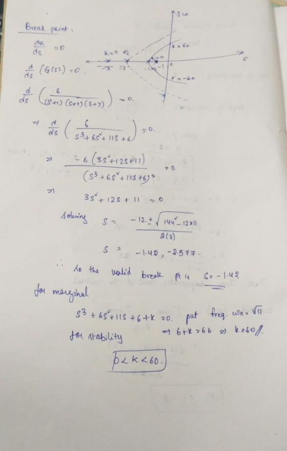
Consider a unity feedback control system with open loop transfer function KG(G) s(s+2)(s + 6) 1....
 Consider a unity feedback control system with open loop transfer function KG(G) s(s+2)(s + 6) 1. Write the characteristic equation of the system 2. Determine the open loop poles and open loop zeros of the system 3. Are there any zeros in infinity? If yes, how many? 4. Sketch the segments of root locus on real axis 5. Determine and sketch the center and the angles of the asymptotes
Sketch the root locus plot of a unity feedback system with an open loop transfer function...
Sketch the root locus plot of a unity feedback system with an open loop transfer function G(s) = K / s (s+2) (s+4) Determine the value of K so that the dominant pair of complex poles of the system has a damping ratio of 0.5.
Sketch the root locus for the unity feedback system shown in Figure P8.3 for the following...
 Sketch the root locus for the unity feedback system shown in Figure P8.3 for the following transfer functions: (Section: 8.4] K(s + 2)(8 + 6) a. G(s) = 52 + 8 + 25 K( +4) b. G(S) = FIGURE PR3 152 +1) C G(s) - K(s+1) K (n1)(x + 4) For each system record all steps to sketching the root locus: 1) Identify the # of branches of the system 2) Make sure your sketch is symmetric about the real-axis...
[7] Sketch the root locus for the unity feedback system whose open loop transfer function is K G(s) Draw the root lo...
 [7] Sketch the root locus for the unity feedback system whose open loop transfer function is K G(s) Draw the root locus of the system with the gain Kas a variable. s(s+4) (s2+4s+20) Determine asymptotes, centroid, breakaway point, angle of departure, and the gain at which root locus crosses ja-axis. A control system with type-0 process and a PID controller is shown below. Design the [8 parameters of the PID controller so that the following specifications are satisfied. =100 a)...
Lectures 15-18: Root-locus method 5.1 Sketch the root locus for a unity feedback system with the ...
 help on #5.2
L(s) is loop transfer function
1+L(s) = 0
lecture notes:
Lectures 15-18: Root-locus method 5.1 Sketch the root locus for a unity feedback system with the loop transfer function (8+5(+10) .2 +10+20 where K, T, and a are nonnegative parameters. For each case summarize your results in a table similar to the one provided below. Root locus parameters Open loop poles Open loop zeros Number of zeros at infinity Number of branches Number of asymptotes Center of...
help on #5.2
L(s) is loop transfer function
1+L(s) = 0
lecture notes:
Lectures 15-18: Root-locus method 5.1 Sketch the root locus for a unity feedback system with the loop transfer function (8+5(+10) .2 +10+20 where K, T, and a are nonnegative parameters. For each case summarize your results in a table similar to the one provided below. Root locus parameters Open loop poles Open loop zeros Number of zeros at infinity Number of branches Number of asymptotes Center of...
Consider the unity feedback system is given below R(S) C(s) G(s) with transfer function: G() =...
 Consider the unity feedback system is given below R(S) C(s) G(s) with transfer function: G() = K(+2) s(s+ 1/s + 3)(+5) a) Sketch the root locus. Clearly indicate any asymptotes. b) Find the value of the gain K, that will make the system marginally stable. c) Find the value of the gain K, for which the closed-loop transfer function will have a pole on the real axis at (-0.5).
A plant with the transfer function Gp(s)-- with unity feedback has the root locus shown in the figure below: (s+2)(s+4) Root Locus 1.5 C(s) 0.5 0.5 1.5 .3 Real Axis (seconds) (a) Determine K of G...
 A plant with the transfer function Gp(s)-- with unity feedback has the root locus shown in the figure below: (s+2)(s+4) Root Locus 1.5 C(s) 0.5 0.5 1.5 .3 Real Axis (seconds) (a) Determine K of Gp(s) if it is desired that the uncompensated system has a 10% OS (overshoot) to a step input. (4 points) a 5% overshoot and a peak time Tp 3.1 meets the requirements described in part (b) and achieves zero steady state (b) Compute the desired...
 oble2 (25 Pts.) Root Locus: A proportional only action is controlling a plant with unity feedback. The plant ansfer function is: 6 GG)s+ 1)s + 2)s +3) a. Draw the poles of G(s) in below figure b. How many asymptotes does the root locus plot of the above transfer function has? c. What angles do the asymptotes make with the positive real axis in the s plane? d. At what point do the asymptotes intersect on the real axis? e....
 Problem 2 For the unity feedback system below in Figure 2 G(s) Figure 2. With (8+2) G(s) = (a) Sketch the root locus. 1. Draw the finite open-loop poles and zeros. ii. Draw the real-axis root locus iii. Draw the asymptotes and root locus branches. (b) Find the value of gain that will make the system marginally stable. (c) Find the value of gain for which the closed-loop transfer function will have a pole on the real axis at s...
 [7] Sketch the root locus for the unity feedback system whose open loop transfer function is K G(s) Draw the root locus of the system with the gain K as a variable s(s+4) (s2+4s+20)' Determine asymptotes, centroid,, breakaway point, angle of departure, and the gain at which root locus crosses jw -axis.
[7] Sketch the root locus for the unity feedback system whose open loop transfer function is K G(s) Draw the root locus of the system with the gain...
[7] Sketch the root locus for the unity feedback system whose open loop transfer function is K G(s) Draw the root locus of the system with the gain K as a variable s(s+4) (s2+4s+20)' Determine asymptotes, centroid,, breakaway point, angle of departure, and the gain at which root locus crosses jw -axis.
[7] Sketch the root locus for the unity feedback system whose open loop transfer function is K G(s) Draw the root locus of the system with the gain...
 Consider a unity feedback control system with open loop transfer function KG(G) s(s+2)(s + 6) 1. Write the characteristic equation of the system 2. Determine the open loop poles and open loop zeros of the system 3. Are there any zeros in infinity? If yes, how many? 4. Sketch the segments of root locus on real axis 5. Determine and sketch the center and the angles of the asymptotes
 Sketch the root locus for the unity feedback system shown in Figure P8.3 for the following transfer functions: (Section: 8.4] K(s + 2)(8 + 6) a. G(s) = 52 + 8 + 25 K( +4) b. G(S) = FIGURE PR3 152 +1) C G(s) - K(s+1) K (n1)(x + 4) For each system record all steps to sketching the root locus: 1) Identify the # of branches of the system 2) Make sure your sketch is symmetric about the real-axis...
 [7] Sketch the root locus for the unity feedback system whose open loop transfer function is K G(s) Draw the root locus of the system with the gain Kas a variable. s(s+4) (s2+4s+20) Determine asymptotes, centroid, breakaway point, angle of departure, and the gain at which root locus crosses ja-axis. A control system with type-0 process and a PID controller is shown below. Design the [8 parameters of the PID controller so that the following specifications are satisfied. =100 a)...
 help on #5.2
L(s) is loop transfer function
1+L(s) = 0
lecture notes:
Lectures 15-18: Root-locus method 5.1 Sketch the root locus for a unity feedback system with the loop transfer function (8+5(+10) .2 +10+20 where K, T, and a are nonnegative parameters. For each case summarize your results in a table similar to the one provided below. Root locus parameters Open loop poles Open loop zeros Number of zeros at infinity Number of branches Number of asymptotes Center of...
help on #5.2
L(s) is loop transfer function
1+L(s) = 0
lecture notes:
Lectures 15-18: Root-locus method 5.1 Sketch the root locus for a unity feedback system with the loop transfer function (8+5(+10) .2 +10+20 where K, T, and a are nonnegative parameters. For each case summarize your results in a table similar to the one provided below. Root locus parameters Open loop poles Open loop zeros Number of zeros at infinity Number of branches Number of asymptotes Center of...
 Consider the unity feedback system is given below R(S) C(s) G(s) with transfer function: G() = K(+2) s(s+ 1/s + 3)(+5) a) Sketch the root locus. Clearly indicate any asymptotes. b) Find the value of the gain K, that will make the system marginally stable. c) Find the value of the gain K, for which the closed-loop transfer function will have a pole on the real axis at (-0.5).
 A plant with the transfer function Gp(s)-- with unity feedback has the root locus shown in the figure below: (s+2)(s+4) Root Locus 1.5 C(s) 0.5 0.5 1.5 .3 Real Axis (seconds) (a) Determine K of Gp(s) if it is desired that the uncompensated system has a 10% OS (overshoot) to a step input. (4 points) a 5% overshoot and a peak time Tp 3.1 meets the requirements described in part (b) and achieves zero steady state (b) Compute the desired...
Most questions answered within 3 hours.
-
Where is the error in this code sequence?
String s1 = "Hello";
String s2 = "ello";...
asked 11 months ago -
Financial data for Joel de Paris, Inc., for last year
follow:
Joel de Paris, Inc.
Balance...
asked 11 months ago -
Consider this reaction:
Al2(SO4)3 (aq)+ BaCl3
(aq) Al2Cl6 (aq)- +
3BaSO4(s) . What is the...
asked 11 months ago -
Suppose that Savneet is considering increasing her
recent random sample from 20 car rentals to 40...
asked 11 months ago -
Trucks arrive at an unloading terminal at an average rate of 120
per hour.
Trucks arrive...
asked 11 months ago -
Why are methanol and ethanol completely soluble in water while
octanol is not very little soluble....
asked 11 months ago -
A facilities manager at a university reads in a research report
that the mean amount of...
asked 11 months ago -
When the CuSO4 is rehydrated by adding water to the anhydrous
compound, is this an endothermic...
asked 11 months ago -
A ray of sunlight is passing from diamond into crown glass; the
angle of incidence is...
asked 11 months ago -
A block of mass 0.249 kg is placed on top of a light, vertical
spring of...
asked 11 months ago -
how do the kidneys compensate in the presences of acidosis
a) trigger hyperventilate
b) reserve acid...
asked 11 months ago -
Question 501 pts
The rental rate of capital to the firm increases. Which of the
following...
asked 11 months ago