Can you please solve the following question.
Regards
Homework Answers


Add Answer to:
Can you please solve the following question. Regards Hi Can you please solve Problem 3-24 on page 154 of Daryll Logan, A...
3.24 Determine the nodal displacements and the element forces for the truss shown in Figure P3-24. Assume all elements have the same AE 4 15 m 4 2 20 m Figure P3-24 3.24 Determine the nodal...
 3.24 Determine the nodal displacements and the element forces for the truss shown in Figure P3-24. Assume all elements have the same AE 4 15 m 4 2 20 m Figure P3-24
3.24 Determine the nodal displacements and the element forces for the truss shown in Figure P3-24. Assume all elements have the same AE
4 15 m 4 2 20 m Figure P3-24
3.24 Determine the nodal displacements and the element forces for the truss shown in Figure P3-24. Assume all elements have the same AE 4 15 m 4 2 20 m Figure P3-24
3.24 Determine the nodal displacements and the element forces for the truss shown in Figure P3-24. Assume all elements have the same AE
4 15 m 4 2 20 m Figure P3-24
Solve all problems using the finite element stiffness method. For the rigid frame shown in Figure P5-4, determine (1) the nodal displacements and rotation at node 4, (2) the reactions, and (3) the fo...
 Solve all problems using the finite element stiffness method. For the rigid frame shown in Figure P5-4, determine (1) the nodal displacements and rotation at node 4, (2) the reactions, and (3) the forces in each element. Then check equilibrium at node 4 Finally, draw the shear force and bending moment diagrams for each element. Let E 30x 103 ksi, A 8 in2, and I 800 in.4 for all elements. 20 kip 25 ft 25 ft 40 ft Figure P5-4...
Problem 4. (3 points). Determine the nodal displacements and reaction forces using the finite ele...
 Problem 4. (3 points). Determine the nodal displacements and reaction forces using the finite element direct method for the 1-D bar elements connected as shown below. Do not rename the nodes or elements when solving. Assume that bars can only undergo translation in x (1 DOF at each node). Nodes 1 and 4 are fixed Elements 1, 2 and 3 have Young's Modulus of Ei-300 Pa, E2-200 Pa, Es-200 Pa. All elements have o ae of 20 N 20 N...
Figure Q5(a) shows a plane truss supported by a horizontal spring at the top node. The...
 Figure Q5(a) shows a plane truss supported by a horizontal spring at the top node. The truss members are of a solid circular cross section having a diameter of 20 mm and an elastic modulus (E) of 80 GPa (10° N/m2). The spring has a stiffness constant of k-2000 kN/m. A point load of 15 kN is applied at the top node. The direction of the load is indicated in the figure. The code numbers for elements, nodes, DOFS, and...
Solve all problems using the finite element stiffness method. For the rigid frame shown in Figure...
 Solve all problems using the finite element stiffness method. For the rigid frame shown in Figure P5-4, determine (1) the nodal displacements and rotation at node 4, (2) the reactions, and (3) the forces in each element. Then check equilibrium at node 4. Finally, draw the shear force and bending moment diagrams for each element. LetE 30 x 103 ksi, A = 8 in,2 , and 1-800 in.4 for all elements. 20 kip 25 ft 25 ft- 40 ft 20...
Mid-Term # 2 for MAE409A, Sec 3, 3/28/2019 Student Name& ID: Instructor: Dr. George Tzong Problem...
 Mid-Term # 2 for MAE409A, Sec 3, 3/28/2019 Student Name& ID: Instructor: Dr. George Tzong Problem i (1196): Please use one dimensional finite elem by following Element and Node IDs as defined in the figure. Node 3 is fixed, and Nodes 3 and 4 are 2 units away from rigid walls. (1) Assemble and show the reduced global stiffhess matrix and load vector for the model; and (2) Find the nodal displacements, reaction forces at Node 1, and stress in...
t is given that E 29.5 x 10 psi and 3- Consider the four-bar truss shown...
 t is given that E 29.5 x 10 psi and 3- Consider the four-bar truss shown in the figure below Ae 1 in2 for all elements (a) Determine the element stiffness matrix for each element. (b) Assemble the global stiffhness matrix for the entire truss. (c) Using the elimination approach, solve for the nodal displacement. (d) Calculate the reaction forces (25 points) 25000 lb 4 4 30 in. 2 20000 lb _40 in.
Please solve this question clearly and step by step. Thank you 2. A truss assembly shown...
 Please solve this question clearly and step by step.
Thank you
2. A truss assembly shown in Figure Q2 below is made of aluminum alloy that has a modulus of elasticity, E = 69 GPa. member is 225 mm2 The cross sectional area of each 4300 N (0, 40) m (40, 40) m 2 500 N 3 (0, 0) FIGURE Q2 Determine the global stiffness matrix for the truss assembly. a. [10 marks] Determine the displacement at node 3. b....
Please solve this question clearly and step by step.
Thank you
2. A truss assembly shown in Figure Q2 below is made of aluminum alloy that has a modulus of elasticity, E = 69 GPa. member is 225 mm2 The cross sectional area of each 4300 N (0, 40) m (40, 40) m 2 500 N 3 (0, 0) FIGURE Q2 Determine the global stiffness matrix for the truss assembly. a. [10 marks] Determine the displacement at node 3. b....
!!USING ABAQUS SOFTWARE!! :- Please solve the following question using ABAQUS software to analyse the behaviour...
 !!USING ABAQUS SOFTWARE!! :-
Please solve the following question using ABAQUS software to
analyse the behaviour of the truss.
Figure 1 shows a truss frame. The frame consists of three elements. All the elements have the same material properties and these are listed in Table 1. Young's Modulus, E Poisson ratio, v Diameter of circular profile, d Length L E=260 GPa v=0.35 d=20mm See Figure 1 Table 1: Truss Frame Properties 20kN 30 3m 120° 3m Figure 1: Truss Frame...
!!USING ABAQUS SOFTWARE!! :-
Please solve the following question using ABAQUS software to
analyse the behaviour of the truss.
Figure 1 shows a truss frame. The frame consists of three elements. All the elements have the same material properties and these are listed in Table 1. Young's Modulus, E Poisson ratio, v Diameter of circular profile, d Length L E=260 GPa v=0.35 d=20mm See Figure 1 Table 1: Truss Frame Properties 20kN 30 3m 120° 3m Figure 1: Truss Frame...
Solve the following truss problem. All truss members are ANSI 2x2x0.25 hollow square tubes (with rounded...
 Solve the following truss problem. All truss members are ANSI 2x2x0.25 hollow square tubes (with rounded corners) for which the cross-section area is A-1.5891 in2. The material has a modulus of E-29E6 psi. Length of element 1 and 5 is L-20 inches, and length of element 3 and 6 is 2L 40 inches. 7 5 6 P-1000 lb 2. 1. Solve in an Excel spreadsheet using the truss element. Note that there are only four different element stiffness matrices (look...
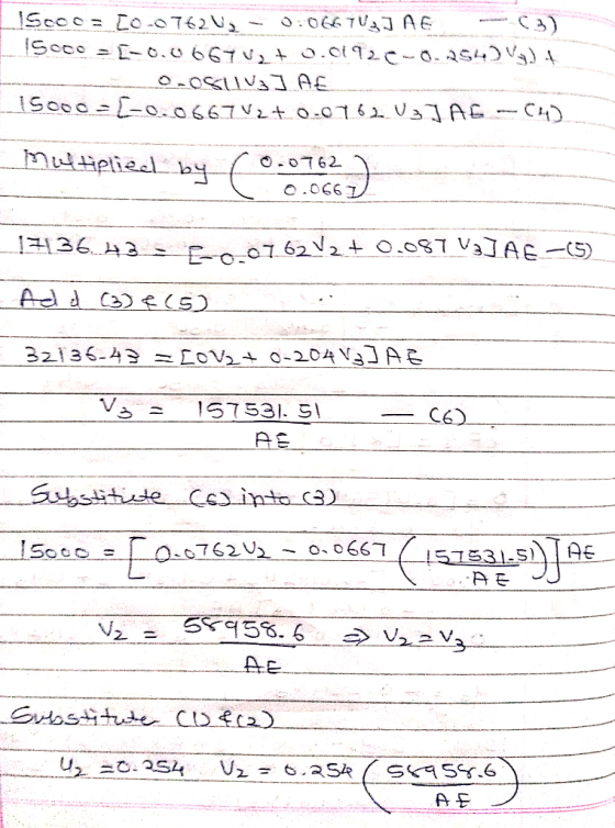
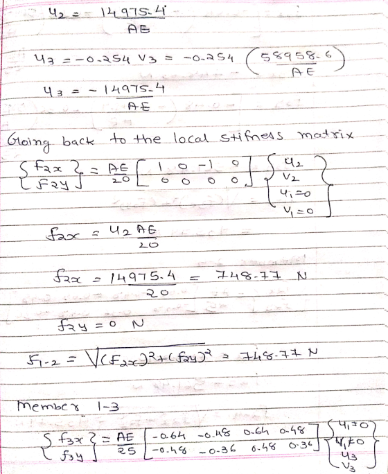
 3.24 Determine the nodal displacements and the element forces for the truss shown in Figure P3-24. Assume all elements have the same AE 4 15 m 4 2 20 m Figure P3-24
3.24 Determine the nodal displacements and the element forces for the truss shown in Figure P3-24. Assume all elements have the same AE
4 15 m 4 2 20 m Figure P3-24
3.24 Determine the nodal displacements and the element forces for the truss shown in Figure P3-24. Assume all elements have the same AE 4 15 m 4 2 20 m Figure P3-24
3.24 Determine the nodal displacements and the element forces for the truss shown in Figure P3-24. Assume all elements have the same AE
4 15 m 4 2 20 m Figure P3-24
 Solve all problems using the finite element stiffness method. For the rigid frame shown in Figure P5-4, determine (1) the nodal displacements and rotation at node 4, (2) the reactions, and (3) the forces in each element. Then check equilibrium at node 4 Finally, draw the shear force and bending moment diagrams for each element. Let E 30x 103 ksi, A 8 in2, and I 800 in.4 for all elements. 20 kip 25 ft 25 ft 40 ft Figure P5-4...
 Problem 4. (3 points). Determine the nodal displacements and reaction forces using the finite element direct method for the 1-D bar elements connected as shown below. Do not rename the nodes or elements when solving. Assume that bars can only undergo translation in x (1 DOF at each node). Nodes 1 and 4 are fixed Elements 1, 2 and 3 have Young's Modulus of Ei-300 Pa, E2-200 Pa, Es-200 Pa. All elements have o ae of 20 N 20 N...
 Figure Q5(a) shows a plane truss supported by a horizontal spring at the top node. The truss members are of a solid circular cross section having a diameter of 20 mm and an elastic modulus (E) of 80 GPa (10° N/m2). The spring has a stiffness constant of k-2000 kN/m. A point load of 15 kN is applied at the top node. The direction of the load is indicated in the figure. The code numbers for elements, nodes, DOFS, and...
 Solve all problems using the finite element stiffness method. For the rigid frame shown in Figure P5-4, determine (1) the nodal displacements and rotation at node 4, (2) the reactions, and (3) the forces in each element. Then check equilibrium at node 4. Finally, draw the shear force and bending moment diagrams for each element. LetE 30 x 103 ksi, A = 8 in,2 , and 1-800 in.4 for all elements. 20 kip 25 ft 25 ft- 40 ft 20...
 Mid-Term # 2 for MAE409A, Sec 3, 3/28/2019 Student Name& ID: Instructor: Dr. George Tzong Problem i (1196): Please use one dimensional finite elem by following Element and Node IDs as defined in the figure. Node 3 is fixed, and Nodes 3 and 4 are 2 units away from rigid walls. (1) Assemble and show the reduced global stiffhess matrix and load vector for the model; and (2) Find the nodal displacements, reaction forces at Node 1, and stress in...
 t is given that E 29.5 x 10 psi and 3- Consider the four-bar truss shown in the figure below Ae 1 in2 for all elements (a) Determine the element stiffness matrix for each element. (b) Assemble the global stiffhness matrix for the entire truss. (c) Using the elimination approach, solve for the nodal displacement. (d) Calculate the reaction forces (25 points) 25000 lb 4 4 30 in. 2 20000 lb _40 in.
 Please solve this question clearly and step by step.
Thank you
2. A truss assembly shown in Figure Q2 below is made of aluminum alloy that has a modulus of elasticity, E = 69 GPa. member is 225 mm2 The cross sectional area of each 4300 N (0, 40) m (40, 40) m 2 500 N 3 (0, 0) FIGURE Q2 Determine the global stiffness matrix for the truss assembly. a. [10 marks] Determine the displacement at node 3. b....
Please solve this question clearly and step by step.
Thank you
2. A truss assembly shown in Figure Q2 below is made of aluminum alloy that has a modulus of elasticity, E = 69 GPa. member is 225 mm2 The cross sectional area of each 4300 N (0, 40) m (40, 40) m 2 500 N 3 (0, 0) FIGURE Q2 Determine the global stiffness matrix for the truss assembly. a. [10 marks] Determine the displacement at node 3. b....
 !!USING ABAQUS SOFTWARE!! :-
Please solve the following question using ABAQUS software to
analyse the behaviour of the truss.
Figure 1 shows a truss frame. The frame consists of three elements. All the elements have the same material properties and these are listed in Table 1. Young's Modulus, E Poisson ratio, v Diameter of circular profile, d Length L E=260 GPa v=0.35 d=20mm See Figure 1 Table 1: Truss Frame Properties 20kN 30 3m 120° 3m Figure 1: Truss Frame...
!!USING ABAQUS SOFTWARE!! :-
Please solve the following question using ABAQUS software to
analyse the behaviour of the truss.
Figure 1 shows a truss frame. The frame consists of three elements. All the elements have the same material properties and these are listed in Table 1. Young's Modulus, E Poisson ratio, v Diameter of circular profile, d Length L E=260 GPa v=0.35 d=20mm See Figure 1 Table 1: Truss Frame Properties 20kN 30 3m 120° 3m Figure 1: Truss Frame...
 Solve the following truss problem. All truss members are ANSI 2x2x0.25 hollow square tubes (with rounded corners) for which the cross-section area is A-1.5891 in2. The material has a modulus of E-29E6 psi. Length of element 1 and 5 is L-20 inches, and length of element 3 and 6 is 2L 40 inches. 7 5 6 P-1000 lb 2. 1. Solve in an Excel spreadsheet using the truss element. Note that there are only four different element stiffness matrices (look...
Most questions answered within 3 hours.
-
Where is the error in this code sequence?
String s1 = "Hello";
String s2 = "ello";...
asked 10 months ago -
Financial data for Joel de Paris, Inc., for last year
follow:
Joel de Paris, Inc.
Balance...
asked 10 months ago -
Consider this reaction:
Al2(SO4)3 (aq)+ BaCl3
(aq) Al2Cl6 (aq)- +
3BaSO4(s) . What is the...
asked 10 months ago -
Suppose that Savneet is considering increasing her
recent random sample from 20 car rentals to 40...
asked 10 months ago -
Trucks arrive at an unloading terminal at an average rate of 120
per hour.
Trucks arrive...
asked 10 months ago -
Why are methanol and ethanol completely soluble in water while
octanol is not very little soluble....
asked 10 months ago -
A facilities manager at a university reads in a research report
that the mean amount of...
asked 10 months ago -
When the CuSO4 is rehydrated by adding water to the anhydrous
compound, is this an endothermic...
asked 10 months ago -
A ray of sunlight is passing from diamond into crown glass; the
angle of incidence is...
asked 10 months ago -
A block of mass 0.249 kg is placed on top of a light, vertical
spring of...
asked 10 months ago -
how do the kidneys compensate in the presences of acidosis
a) trigger hyperventilate
b) reserve acid...
asked 10 months ago -
Question 501 pts
The rental rate of capital to the firm increases. Which of the
following...
asked 10 months ago