
Homework Answers

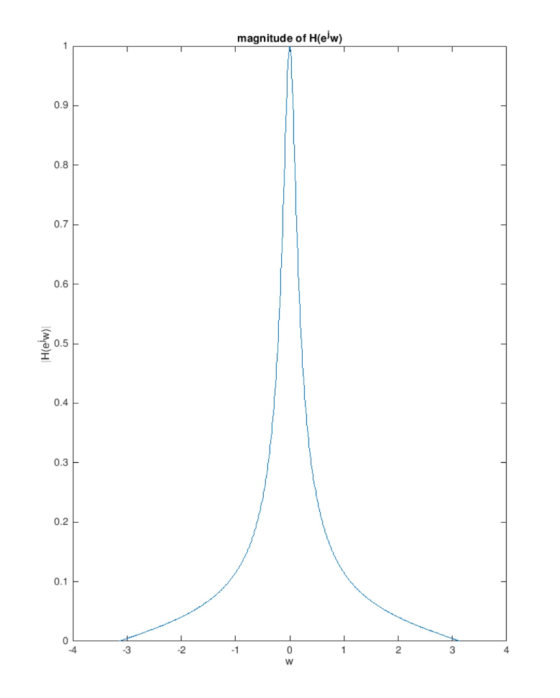
Magnitude response:

Add Answer to:
ter with the following structure 1. Design an IR low-pass fil Where a, b, c.are free parameters that are designed to...
1. By using an analog filter with a Butterworth response of order 3, design a digital IIR low pass filter with 3-db cutoff frequency 2c 0.6TT a) b) c) Evaluate the transfer function of the analog fil...
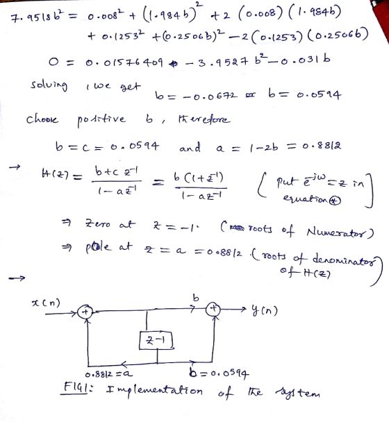
 1. By using an analog filter with a Butterworth response of order 3, design a digital IIR low pass filter with 3-db cutoff frequency 2c 0.6TT a) b) c) Evaluate the transfer function of the analog filter (10marks) Skecth the block diagram of transfer function (5 marks) Plot the magnitude response of the filters. (5marks)
1. By using an analog filter with a Butterworth response of order 3, design a digital IIR low pass filter with 3-db cutoff frequency 2c...
1. By using an analog filter with a Butterworth response of order 3, design a digital IIR low pass filter with 3-db cutoff frequency 2c 0.6TT a) b) c) Evaluate the transfer function of the analog filter (10marks) Skecth the block diagram of transfer function (5 marks) Plot the magnitude response of the filters. (5marks)
1. By using an analog filter with a Butterworth response of order 3, design a digital IIR low pass filter with 3-db cutoff frequency 2c...
1) Design a low-pass RC device with the following specifications: a) Input x(t) and output y(t)...
1) Design a low-pass RC device with the following specifications: a) Input x(t) and output y(t) b) Bandwidth which is defined as the range of frequencies (from 0 Hz to ??, the − 3dB point ) allowed to pass through without significant attenuation = 100Hz c) Static gain = 14dB d) The system has −20 dB/decade rolloff at high frequencies (thus first-order LP filter) Assume that you have one and only one resistor value available to you, and that resistance is...
A. Design a low-pass filter (op-amp based cascade design) that meets the following (30) requirements: 1. Cutoff frequency: 3.4 KHz Passband gain: 20 dB 2. 3. Stopband gain: -40 dB/decade 4. All re...
 A. Design a low-pass filter (op-amp based cascade design) that meets the following (30) requirements: 1. Cutoff frequency: 3.4 KHz Passband gain: 20 dB 2. 3. Stopband gain: -40 dB/decade 4. All resistors must be 1.0 kS2 or higher. You have completed the design and implementation of the LP filter and are ready to deliver the filter for production. However, you are informed that the customer made a mistake and actually needed a stopband gain of -60 dB/decade (not-40 dB/decade...
A. Design a low-pass filter (op-amp based cascade design) that meets the following (30) requirements 1. Cutoff frequency: 3.4 KHz 2. Passband gain: 20 dB 3. Stopband gain: -40 dB/decade 4. All re...
 A. Design a low-pass filter (op-amp based cascade design) that meets the following (30) requirements 1. Cutoff frequency: 3.4 KHz 2. Passband gain: 20 dB 3. Stopband gain: -40 dB/decade 4. All resistors must be 1.0 k2 or higher. You have completed the design and implementation of the LP filter and are ready to deliver the filter for production. However, you are informed that the customer made a mistake and actually needed a stopb you have used in your design)....
 1. By using an analog filter with a Butterworth response of order 3, design a digital IIR low pass filter with 3-db cutoff frequency 2c 0.6TT a) b) c) Evaluate the transfer function of the analog filter (10marks) Skecth the block diagram of transfer function (5 marks) Plot the magnitude response of the filters. (5marks)
1. By using an analog filter with a Butterworth response of order 3, design a digital IIR low pass filter with 3-db cutoff frequency 2c...
1. By using an analog filter with a Butterworth response of order 3, design a digital IIR low pass filter with 3-db cutoff frequency 2c 0.6TT a) b) c) Evaluate the transfer function of the analog filter (10marks) Skecth the block diagram of transfer function (5 marks) Plot the magnitude response of the filters. (5marks)
1. By using an analog filter with a Butterworth response of order 3, design a digital IIR low pass filter with 3-db cutoff frequency 2c...
 A. Design a low-pass filter (op-amp based cascade design) that meets the following (30) requirements: 1. Cutoff frequency: 3.4 KHz Passband gain: 20 dB 2. 3. Stopband gain: -40 dB/decade 4. All resistors must be 1.0 kS2 or higher. You have completed the design and implementation of the LP filter and are ready to deliver the filter for production. However, you are informed that the customer made a mistake and actually needed a stopband gain of -60 dB/decade (not-40 dB/decade...
 A. Design a low-pass filter (op-amp based cascade design) that meets the following (30) requirements 1. Cutoff frequency: 3.4 KHz 2. Passband gain: 20 dB 3. Stopband gain: -40 dB/decade 4. All resistors must be 1.0 k2 or higher. You have completed the design and implementation of the LP filter and are ready to deliver the filter for production. However, you are informed that the customer made a mistake and actually needed a stopb you have used in your design)....
Most questions answered within 3 hours.
-
Where is the error in this code sequence?
String s1 = "Hello";
String s2 = "ello";...
asked 10 months ago -
Financial data for Joel de Paris, Inc., for last year
follow:
Joel de Paris, Inc.
Balance...
asked 10 months ago -
Consider this reaction:
Al2(SO4)3 (aq)+ BaCl3
(aq) Al2Cl6 (aq)- +
3BaSO4(s) . What is the...
asked 10 months ago -
Suppose that Savneet is considering increasing her
recent random sample from 20 car rentals to 40...
asked 10 months ago -
Trucks arrive at an unloading terminal at an average rate of 120
per hour.
Trucks arrive...
asked 10 months ago -
Why are methanol and ethanol completely soluble in water while
octanol is not very little soluble....
asked 10 months ago -
A facilities manager at a university reads in a research report
that the mean amount of...
asked 10 months ago -
When the CuSO4 is rehydrated by adding water to the anhydrous
compound, is this an endothermic...
asked 10 months ago -
A ray of sunlight is passing from diamond into crown glass; the
angle of incidence is...
asked 10 months ago -
A block of mass 0.249 kg is placed on top of a light, vertical
spring of...
asked 10 months ago -
how do the kidneys compensate in the presences of acidosis
a) trigger hyperventilate
b) reserve acid...
asked 10 months ago -
Question 501 pts
The rental rate of capital to the firm increases. Which of the
following...
asked 10 months ago