
Full working and explanation please
Homework Answers

![ореи lооp тA 3Dy (st1) St42 (S)(#10) Closed hoop TF 30oy (st) ]t) (st1) (st2) Hs) Зооч (St) ( St1) (st1o) (St4 2) + 3D4 4(st1](http://img.homeworklib.com/images/444b814a-fc7c-41a6-b9e9-6e9994162586.png?x-oss-process=image/resize,w_560)
Add Answer to:
Full working and explanation please (15 Points 15. First Order Lead/Lag Compensation Consider first-order digital compe...
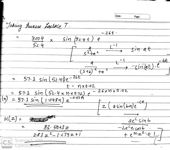
Give me the explanation plz 2. a) A digital controller implementation for a feedback system is shown in Figure 2 where the sampling period is T0.1 second. The plant transfer function is s +10 P(s) =...
 Give me the explanation plz
2. a) A digital controller implementation for a feedback system is shown in Figure 2 where the sampling period is T0.1 second. The plant transfer function is s +10 P(s) = and the feedback controller, K, is a simple proportional gain (K>0).v R(z) E(z) S+10 Controller ZOH Plant Figure 2* i)o In order to directly design a digital controller in the z-domain, the plant P(s) 6. needs to be discretised as P(z). Find the ZOH...
Give me the explanation plz
2. a) A digital controller implementation for a feedback system is shown in Figure 2 where the sampling period is T0.1 second. The plant transfer function is s +10 P(s) = and the feedback controller, K, is a simple proportional gain (K>0).v R(z) E(z) S+10 Controller ZOH Plant Figure 2* i)o In order to directly design a digital controller in the z-domain, the plant P(s) 6. needs to be discretised as P(z). Find the ZOH...
Lag Compensator Design Using Root-Locus 2. Consider the unity feedback system in Figure 1 for G(s...
 Lag Compensator Design Using Root-Locus 2. Consider the unity feedback system in Figure 1 for G(s)- s(s+3(s6) Design a lag compensation to meet the following specifications The step response settling time is to be less than 5 sec. . The step response overshoot is to be less than 17% . The steady-state error to a unit ramp input must not exceed 10%. Dynamic specifications (overshoot and settling time) can be met using proportional feedback, but a lag compensator is needed...
I have no more posting for this month, please solve these for me thanks 1. Given...
 I have no more posting for this month, please solve these for me
thanks
1. Given the following unity feedback system where s+z s2 (s + 10) and the controller is a proportional controller Ge = K, do the following: a. If z = 2, find K so that the damped frequency of the oscillation of the transient response is 5 rad/s. b. The system is to be redesigned by changing the values of z and K. If the new...
I have no more posting for this month, please solve these for me
thanks
1. Given the following unity feedback system where s+z s2 (s + 10) and the controller is a proportional controller Ge = K, do the following: a. If z = 2, find K so that the damped frequency of the oscillation of the transient response is 5 rad/s. b. The system is to be redesigned by changing the values of z and K. If the new...
I need help with this, provide clear answers, please. Thanks in advance. By gain compensation, the...
 I need help with this, provide clear answers, please. Thanks in
advance.
By gain compensation, the following system operates with a 19.3% overshoot when K- 281.69, Design a lead compensator to reduce the percentage overshoot to 10% and reduce the settling time by 1 sec. R(s) C(s) 4 +6)s +8) (c) Fill out the table below. (d) Simulate the step response to validate if the design goal is met. Compensated system with the lead compensator Uncompensated system Overall gain Dominant...
I need help with this, provide clear answers, please. Thanks in
advance.
By gain compensation, the following system operates with a 19.3% overshoot when K- 281.69, Design a lead compensator to reduce the percentage overshoot to 10% and reduce the settling time by 1 sec. R(s) C(s) 4 +6)s +8) (c) Fill out the table below. (d) Simulate the step response to validate if the design goal is met. Compensated system with the lead compensator Uncompensated system Overall gain Dominant...
Problem 5: Suppose that you are to design a unity gain feedback controller for a first order plant. The plant...
 Problem 5: Suppose that you are to design a unity gain feedback controller for a first order plant. The plant and controller respectively take the form ,s+ p where K> 0, p. z are parameters to be specified. (a) Using root-locus methods, specify some p and z for which it is possible to make the closed-loop system strictly stable. Include a sketch of the closed-loop root locus, as well as the corresponding range of gains K for which the system...
20 points] Q1. The Stately State Transition Matrix, Ф 16 2 3 13 Consider a state transition matrix, Ф, for a SISO LTI system A1. A- 5 11 10 8 9 76 12 Please determine and justify: (a) Ф(t) for this s...
 20 points] Q1. The Stately State Transition Matrix, Ф 16 2 3 13 Consider a state transition matrix, Ф, for a SISO LTI system A1. A- 5 11 10 8 9 76 12 Please determine and justify: (a) Ф(t) for this system A 4 14 15 1 ] (b) Ф(s) for this system A (c) System A's characteristic polynomial (d) Ф(z) for this system A via Tustin's method (ie, trapazoid-rule) (e) A difference equation assuming: (1) a step input at...
You will look at both 1st and 2nd order approaches as you perform your analysis. Use math lab and Simulink as needed. Please show all calculations and any other means of analysis / simulation for full...
 You will look at both 1st and 2nd order
approaches as you perform your analysis. Use math lab and Simulink
as needed.
Please show all calculations and any other means of analysis /
simulation for full credit.
Question three is the one needed to be solved, but 2 is needed
to solve 3.
Question 2) (25 points) Suppose instead of the cooling chamber modeled as a 1t order system, that the chamber was modeled as a 2nd system due to...
You will look at both 1st and 2nd order
approaches as you perform your analysis. Use math lab and Simulink
as needed.
Please show all calculations and any other means of analysis /
simulation for full credit.
Question three is the one needed to be solved, but 2 is needed
to solve 3.
Question 2) (25 points) Suppose instead of the cooling chamber modeled as a 1t order system, that the chamber was modeled as a 2nd system due to...
Problem 3. (15 points) Consider the feedback system in Figure 3, where G(s)1 (s -1)3 Ge(s)...
 Problem 3. (15 points) Consider the feedback system in Figure 3, where G(s)1 (s -1)3 Ge(s) G(s) Figure 3: Problem 3 1. Let the compensator be given by a pure gain, ie, Ge(s)-K, K 0 (a) Draw the root locus of the compensated system (b) Is it possible to stabilize the systems by selecting K appropriately? If so, find the range for K such that the closed-loop system is BIBO stable. If not, explain. 2. This time, let the compensator...
only b and c please 1 Consider the system whose transfer function is given by: G(S)...
 only b and c please
1 Consider the system whose transfer function is given by: G(S) == (2s +1)(s+3) unction is given by: G(s) - (a) Use the root-locus design methodology to design a lead compensator that will provide a closed-loop damping 5 =0.4 and a natural frequency on =9 rad/sec. The general transfer function for lead compensation is given by D(5)=K (977), p>z, 2=2 (b) Use MATLAB to plot the root locus of the feed-forward transfer function, D(s)*G(s), and...
only b and c please
1 Consider the system whose transfer function is given by: G(S) == (2s +1)(s+3) unction is given by: G(s) - (a) Use the root-locus design methodology to design a lead compensator that will provide a closed-loop damping 5 =0.4 and a natural frequency on =9 rad/sec. The general transfer function for lead compensation is given by D(5)=K (977), p>z, 2=2 (b) Use MATLAB to plot the root locus of the feed-forward transfer function, D(s)*G(s), and...
solve quastion 3,4 and 5 B. Tasks and Guide 1. System description and Mathematical modeling The...
 solve quastion 3,4 and 5
B. Tasks and Guide 1. System description and Mathematical modeling The antenna positioning system is shown in Fig. 1. In this problem we consider the yaw angle control system, where 0(t) is the yaw angle. Suppose that the gain of the power amplifier is 5 , and that the gear ratio and the angle sensor (the shaft encoder and the data hold) are such that (t)= 0.40(t) where the units of v,(t) are volts and...
solve quastion 3,4 and 5
B. Tasks and Guide 1. System description and Mathematical modeling The antenna positioning system is shown in Fig. 1. In this problem we consider the yaw angle control system, where 0(t) is the yaw angle. Suppose that the gain of the power amplifier is 5 , and that the gear ratio and the angle sensor (the shaft encoder and the data hold) are such that (t)= 0.40(t) where the units of v,(t) are volts and...
 Give me the explanation plz
2. a) A digital controller implementation for a feedback system is shown in Figure 2 where the sampling period is T0.1 second. The plant transfer function is s +10 P(s) = and the feedback controller, K, is a simple proportional gain (K>0).v R(z) E(z) S+10 Controller ZOH Plant Figure 2* i)o In order to directly design a digital controller in the z-domain, the plant P(s) 6. needs to be discretised as P(z). Find the ZOH...
Give me the explanation plz
2. a) A digital controller implementation for a feedback system is shown in Figure 2 where the sampling period is T0.1 second. The plant transfer function is s +10 P(s) = and the feedback controller, K, is a simple proportional gain (K>0).v R(z) E(z) S+10 Controller ZOH Plant Figure 2* i)o In order to directly design a digital controller in the z-domain, the plant P(s) 6. needs to be discretised as P(z). Find the ZOH...
 Lag Compensator Design Using Root-Locus 2. Consider the unity feedback system in Figure 1 for G(s)- s(s+3(s6) Design a lag compensation to meet the following specifications The step response settling time is to be less than 5 sec. . The step response overshoot is to be less than 17% . The steady-state error to a unit ramp input must not exceed 10%. Dynamic specifications (overshoot and settling time) can be met using proportional feedback, but a lag compensator is needed...
 I have no more posting for this month, please solve these for me
thanks
1. Given the following unity feedback system where s+z s2 (s + 10) and the controller is a proportional controller Ge = K, do the following: a. If z = 2, find K so that the damped frequency of the oscillation of the transient response is 5 rad/s. b. The system is to be redesigned by changing the values of z and K. If the new...
I have no more posting for this month, please solve these for me
thanks
1. Given the following unity feedback system where s+z s2 (s + 10) and the controller is a proportional controller Ge = K, do the following: a. If z = 2, find K so that the damped frequency of the oscillation of the transient response is 5 rad/s. b. The system is to be redesigned by changing the values of z and K. If the new...
 I need help with this, provide clear answers, please. Thanks in
advance.
By gain compensation, the following system operates with a 19.3% overshoot when K- 281.69, Design a lead compensator to reduce the percentage overshoot to 10% and reduce the settling time by 1 sec. R(s) C(s) 4 +6)s +8) (c) Fill out the table below. (d) Simulate the step response to validate if the design goal is met. Compensated system with the lead compensator Uncompensated system Overall gain Dominant...
I need help with this, provide clear answers, please. Thanks in
advance.
By gain compensation, the following system operates with a 19.3% overshoot when K- 281.69, Design a lead compensator to reduce the percentage overshoot to 10% and reduce the settling time by 1 sec. R(s) C(s) 4 +6)s +8) (c) Fill out the table below. (d) Simulate the step response to validate if the design goal is met. Compensated system with the lead compensator Uncompensated system Overall gain Dominant...
 Problem 5: Suppose that you are to design a unity gain feedback controller for a first order plant. The plant and controller respectively take the form ,s+ p where K> 0, p. z are parameters to be specified. (a) Using root-locus methods, specify some p and z for which it is possible to make the closed-loop system strictly stable. Include a sketch of the closed-loop root locus, as well as the corresponding range of gains K for which the system...
 20 points] Q1. The Stately State Transition Matrix, Ф 16 2 3 13 Consider a state transition matrix, Ф, for a SISO LTI system A1. A- 5 11 10 8 9 76 12 Please determine and justify: (a) Ф(t) for this system A 4 14 15 1 ] (b) Ф(s) for this system A (c) System A's characteristic polynomial (d) Ф(z) for this system A via Tustin's method (ie, trapazoid-rule) (e) A difference equation assuming: (1) a step input at...
 You will look at both 1st and 2nd order
approaches as you perform your analysis. Use math lab and Simulink
as needed.
Please show all calculations and any other means of analysis /
simulation for full credit.
Question three is the one needed to be solved, but 2 is needed
to solve 3.
Question 2) (25 points) Suppose instead of the cooling chamber modeled as a 1t order system, that the chamber was modeled as a 2nd system due to...
You will look at both 1st and 2nd order
approaches as you perform your analysis. Use math lab and Simulink
as needed.
Please show all calculations and any other means of analysis /
simulation for full credit.
Question three is the one needed to be solved, but 2 is needed
to solve 3.
Question 2) (25 points) Suppose instead of the cooling chamber modeled as a 1t order system, that the chamber was modeled as a 2nd system due to...
 Problem 3. (15 points) Consider the feedback system in Figure 3, where G(s)1 (s -1)3 Ge(s) G(s) Figure 3: Problem 3 1. Let the compensator be given by a pure gain, ie, Ge(s)-K, K 0 (a) Draw the root locus of the compensated system (b) Is it possible to stabilize the systems by selecting K appropriately? If so, find the range for K such that the closed-loop system is BIBO stable. If not, explain. 2. This time, let the compensator...
 only b and c please
1 Consider the system whose transfer function is given by: G(S) == (2s +1)(s+3) unction is given by: G(s) - (a) Use the root-locus design methodology to design a lead compensator that will provide a closed-loop damping 5 =0.4 and a natural frequency on =9 rad/sec. The general transfer function for lead compensation is given by D(5)=K (977), p>z, 2=2 (b) Use MATLAB to plot the root locus of the feed-forward transfer function, D(s)*G(s), and...
only b and c please
1 Consider the system whose transfer function is given by: G(S) == (2s +1)(s+3) unction is given by: G(s) - (a) Use the root-locus design methodology to design a lead compensator that will provide a closed-loop damping 5 =0.4 and a natural frequency on =9 rad/sec. The general transfer function for lead compensation is given by D(5)=K (977), p>z, 2=2 (b) Use MATLAB to plot the root locus of the feed-forward transfer function, D(s)*G(s), and...
 solve quastion 3,4 and 5
B. Tasks and Guide 1. System description and Mathematical modeling The antenna positioning system is shown in Fig. 1. In this problem we consider the yaw angle control system, where 0(t) is the yaw angle. Suppose that the gain of the power amplifier is 5 , and that the gear ratio and the angle sensor (the shaft encoder and the data hold) are such that (t)= 0.40(t) where the units of v,(t) are volts and...
solve quastion 3,4 and 5
B. Tasks and Guide 1. System description and Mathematical modeling The antenna positioning system is shown in Fig. 1. In this problem we consider the yaw angle control system, where 0(t) is the yaw angle. Suppose that the gain of the power amplifier is 5 , and that the gear ratio and the angle sensor (the shaft encoder and the data hold) are such that (t)= 0.40(t) where the units of v,(t) are volts and...
Most questions answered within 3 hours.
-
Where is the error in this code sequence?
String s1 = "Hello";
String s2 = "ello";...
asked 10 months ago -
Financial data for Joel de Paris, Inc., for last year
follow:
Joel de Paris, Inc.
Balance...
asked 10 months ago -
Consider this reaction:
Al2(SO4)3 (aq)+ BaCl3
(aq) Al2Cl6 (aq)- +
3BaSO4(s) . What is the...
asked 10 months ago -
Suppose that Savneet is considering increasing her
recent random sample from 20 car rentals to 40...
asked 10 months ago -
Trucks arrive at an unloading terminal at an average rate of 120
per hour.
Trucks arrive...
asked 10 months ago -
Why are methanol and ethanol completely soluble in water while
octanol is not very little soluble....
asked 10 months ago -
A facilities manager at a university reads in a research report
that the mean amount of...
asked 10 months ago -
When the CuSO4 is rehydrated by adding water to the anhydrous
compound, is this an endothermic...
asked 10 months ago -
A ray of sunlight is passing from diamond into crown glass; the
angle of incidence is...
asked 10 months ago -
A block of mass 0.249 kg is placed on top of a light, vertical
spring of...
asked 10 months ago -
how do the kidneys compensate in the presences of acidosis
a) trigger hyperventilate
b) reserve acid...
asked 10 months ago -
Question 501 pts
The rental rate of capital to the firm increases. Which of the
following...
asked 10 months ago