
Homework Answers


Add Answer to:
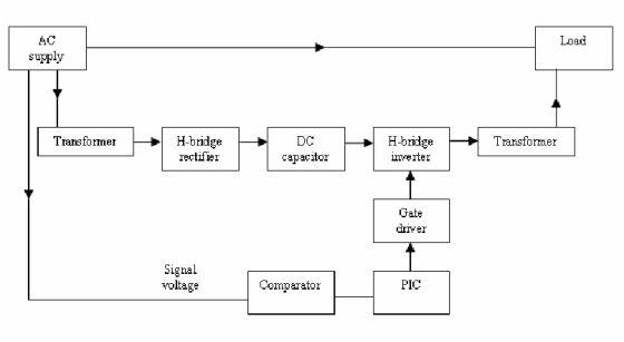
c) Figure 1 shows the block diagram of the UPFC. With the use of the phasor diagrams, explain how the UPFC is operating...
3. Figure 2 shows a single line diagram of a 13.8 kV primary feeder supplying power...
 3. Figure 2 shows a single line diagram of a 13.8 kV primary feeder supplying power to a load at the end of the feeder. A shunt capacitor bank is located at the load bus. The capacitor bank is Y-connected with a reactance Xc = 400/phase. Assume that the voltage at the sending end of the feeder is 5% above rated and theat the load is Y- connected with Ruoad = 200/phase in parallel with load Xload = 400/phase. Determine:...
Figure 1 Single line diagram b2 b3 b1 b4 grid Τι 13 A power system single line diagram is shown...
 Figure 1 Single line diagram b2 b3 b1 b4 grid Τι 13 A power system single line diagram is shown in Figure 1. The single line diagram shows a synchronous generator G connected to a large 50 Hz grid via its unit transformer T and a network of three transmission lines. Relevant details of the grid, transformer, generator and overhead lines are provided in Tables I,II,II & IV respectively. A double line to ground fault occurs at bus 3 Questions....
Figure 1 shows a single-line diagram of a three phase, 60-Hz, synchronous generator, connected th...
 Figure 1 shows a single-line diagram of a three phase, 60-Hz, synchronous generator, connected through a transformer and parallel transmission lines to an infinite bus. All reactances are given in per unit on a common system base. In steady state, the infinite bus receives 1.0 per unit real power at 0.95 power factor lagging. The generator in Figure 1 is initially operating in steady state, when circuit breaker B12 inadvertently opens. Use the equal area criterion to calculate the maximum...
1. Construct to scale a phasor diagram like the one shown in Figure 4 for each of the two cases. Use one sheet of paper and make two separate diagrams on the one sheet. Choose a scale (for exampl...
 1. Construct to scale a phasor diagram like the one shown in Figure 4 for each of the two cases. Use one sheet of paper and make two separate diagrams on the one sheet. Choose a scale (for example, 1.00 v/cm) so that the diagrams are as large as possible, but that each one fits on one- fourth of the sheet of paper. First construct a vector along the x axis with a length scaled to the magnitude of Va,...
Design a FULL WAVE BRIDGE RECTIFIER circuit that will: Take 120volts ac, 60 hz, sinusoidal waveform...
 Design a FULL WAVE BRIDGE RECTIFIER circuit that will:
Take 120volts ac, 60 hz, sinusoidal waveform and convert
it to a “regulated “dc value
giving 12 volts +, - 1 volt across a 2000-ohm output
load resistor with no more than 2%
ripple voltage.
You may assume:
a. An ideal power transformer as discussed in class.
b. For hand computations, you must assume a diode given by
Figure 4.8 page 185.
c. A filter capacitor sized per the textbook equation...
Design a FULL WAVE BRIDGE RECTIFIER circuit that will:
Take 120volts ac, 60 hz, sinusoidal waveform and convert
it to a “regulated “dc value
giving 12 volts +, - 1 volt across a 2000-ohm output
load resistor with no more than 2%
ripple voltage.
You may assume:
a. An ideal power transformer as discussed in class.
b. For hand computations, you must assume a diode given by
Figure 4.8 page 185.
c. A filter capacitor sized per the textbook equation...
Figure 1 shows the one line diagram of a simple power system. Generators are connected at...
 Figure 1 shows the one line diagram of a simple power system. Generators are connected at buses 1 and 3 while the loads are indicated at all five buses. Base values for transmission system are 100 MVA, 138 kV. The line data of Table 1 gives per unit series impedances and the charging MVar accounting for the distributed capacitance of the 5 lines. The bus data in Table 2 list values for P, Q and Vat each bus. The slack...
solve no: 3.14 , 3.16, 3.19 please show each step and solve for beginners 120 Power...
 solve no: 3.14 , 3.16, 3.19
please show each step and solve for beginners
120 Power System Analysis 3.12. A single-phase system similar to that shown in Figure 3.11 has two transformers A-B a B-C connected by a line B feeding a load at the receiving end C. The ratings and parame ter values of the components are 500 V/1.5 kV, 9.6 kVA. leakage reactance 5 % 1.2 kV/120 V, 7.2 kVA, leakage reactance 4 % series impedance (0.5 +...
solve no: 3.14 , 3.16, 3.19
please show each step and solve for beginners
120 Power System Analysis 3.12. A single-phase system similar to that shown in Figure 3.11 has two transformers A-B a B-C connected by a line B feeding a load at the receiving end C. The ratings and parame ter values of the components are 500 V/1.5 kV, 9.6 kVA. leakage reactance 5 % 1.2 kV/120 V, 7.2 kVA, leakage reactance 4 % series impedance (0.5 +...
Preliminary (1.5 marks) 1) Figure 4 shows the block diagram for the resonant servomechanism contr...
 Preliminary (1.5 marks) 1) Figure 4 shows the block diagram for the resonant servomechanism control system. Through out this lab we will be applying proportional control to the system, i.e. C(s)- Kp Controller Fiter L(s) C(s) G(S) Figure 4: Block diagram of control system using proportional control. Equivalent forward Y(s) Figure 5: Block diagram reduced to an equivalent unity feedback system. Determine the equivalent forward transfer function Geg(s), for the equivalent unity feedback system shown in Figure 5, in terms...
Question 1 In the diagram of Superheterodne AM receiver shown below explain the function of each block. (a) 15 marks Antenna Speaker Audio and power amplifiers RF IF Mixer Detector Mi amplifier a...
 Question 1 In the diagram of Superheterodne AM receiver shown below explain the function of each block. (a) 15 marks Antenna Speaker Audio and power amplifiers RF IF Mixer Detector Mi amplifier amplifier AGC --_Local Gang tuned oscillator (b) For a 4-bit DAC, calculate the output voltage for an input code word 1010 if a [10 marks] logic 1 is 10V and a logic 0 is 0V, and R = RFI kΩ Total: 25 marks] Question 2 (a) Explain the...
2. Figure 2 shows a 6-pulse thyristor rectifier feeding a DC static load an operating at steady-state. The ac input power supply is a symmetric set of three-phase voltages forming a direct seque...
 2. Figure 2 shows a 6-pulse thyristor rectifier feeding a DC static load an operating at steady-state. The ac input power supply is a symmetric set of three-phase voltages forming a direct sequence, having rms line-to-line voltage of Vuns equal to 415 V and angular frequency ω equal to 100π rad/s. The load is sufficiently inductive to smooth out the load current i(t), i.e. i 1, where I is a constant. a. Derive the mathematical expression of the average DC...
 3. Figure 2 shows a single line diagram of a 13.8 kV primary feeder supplying power to a load at the end of the feeder. A shunt capacitor bank is located at the load bus. The capacitor bank is Y-connected with a reactance Xc = 400/phase. Assume that the voltage at the sending end of the feeder is 5% above rated and theat the load is Y- connected with Ruoad = 200/phase in parallel with load Xload = 400/phase. Determine:...
 Figure 1 Single line diagram b2 b3 b1 b4 grid Τι 13 A power system single line diagram is shown in Figure 1. The single line diagram shows a synchronous generator G connected to a large 50 Hz grid via its unit transformer T and a network of three transmission lines. Relevant details of the grid, transformer, generator and overhead lines are provided in Tables I,II,II & IV respectively. A double line to ground fault occurs at bus 3 Questions....
 Figure 1 shows a single-line diagram of a three phase, 60-Hz, synchronous generator, connected through a transformer and parallel transmission lines to an infinite bus. All reactances are given in per unit on a common system base. In steady state, the infinite bus receives 1.0 per unit real power at 0.95 power factor lagging. The generator in Figure 1 is initially operating in steady state, when circuit breaker B12 inadvertently opens. Use the equal area criterion to calculate the maximum...
 1. Construct to scale a phasor diagram like the one shown in Figure 4 for each of the two cases. Use one sheet of paper and make two separate diagrams on the one sheet. Choose a scale (for example, 1.00 v/cm) so that the diagrams are as large as possible, but that each one fits on one- fourth of the sheet of paper. First construct a vector along the x axis with a length scaled to the magnitude of Va,...
 Design a FULL WAVE BRIDGE RECTIFIER circuit that will:
Take 120volts ac, 60 hz, sinusoidal waveform and convert
it to a “regulated “dc value
giving 12 volts +, - 1 volt across a 2000-ohm output
load resistor with no more than 2%
ripple voltage.
You may assume:
a. An ideal power transformer as discussed in class.
b. For hand computations, you must assume a diode given by
Figure 4.8 page 185.
c. A filter capacitor sized per the textbook equation...
Design a FULL WAVE BRIDGE RECTIFIER circuit that will:
Take 120volts ac, 60 hz, sinusoidal waveform and convert
it to a “regulated “dc value
giving 12 volts +, - 1 volt across a 2000-ohm output
load resistor with no more than 2%
ripple voltage.
You may assume:
a. An ideal power transformer as discussed in class.
b. For hand computations, you must assume a diode given by
Figure 4.8 page 185.
c. A filter capacitor sized per the textbook equation...
 Figure 1 shows the one line diagram of a simple power system. Generators are connected at buses 1 and 3 while the loads are indicated at all five buses. Base values for transmission system are 100 MVA, 138 kV. The line data of Table 1 gives per unit series impedances and the charging MVar accounting for the distributed capacitance of the 5 lines. The bus data in Table 2 list values for P, Q and Vat each bus. The slack...
 solve no: 3.14 , 3.16, 3.19
please show each step and solve for beginners
120 Power System Analysis 3.12. A single-phase system similar to that shown in Figure 3.11 has two transformers A-B a B-C connected by a line B feeding a load at the receiving end C. The ratings and parame ter values of the components are 500 V/1.5 kV, 9.6 kVA. leakage reactance 5 % 1.2 kV/120 V, 7.2 kVA, leakage reactance 4 % series impedance (0.5 +...
solve no: 3.14 , 3.16, 3.19
please show each step and solve for beginners
120 Power System Analysis 3.12. A single-phase system similar to that shown in Figure 3.11 has two transformers A-B a B-C connected by a line B feeding a load at the receiving end C. The ratings and parame ter values of the components are 500 V/1.5 kV, 9.6 kVA. leakage reactance 5 % 1.2 kV/120 V, 7.2 kVA, leakage reactance 4 % series impedance (0.5 +...
 Preliminary (1.5 marks) 1) Figure 4 shows the block diagram for the resonant servomechanism control system. Through out this lab we will be applying proportional control to the system, i.e. C(s)- Kp Controller Fiter L(s) C(s) G(S) Figure 4: Block diagram of control system using proportional control. Equivalent forward Y(s) Figure 5: Block diagram reduced to an equivalent unity feedback system. Determine the equivalent forward transfer function Geg(s), for the equivalent unity feedback system shown in Figure 5, in terms...
 Question 1 In the diagram of Superheterodne AM receiver shown below explain the function of each block. (a) 15 marks Antenna Speaker Audio and power amplifiers RF IF Mixer Detector Mi amplifier amplifier AGC --_Local Gang tuned oscillator (b) For a 4-bit DAC, calculate the output voltage for an input code word 1010 if a [10 marks] logic 1 is 10V and a logic 0 is 0V, and R = RFI kΩ Total: 25 marks] Question 2 (a) Explain the...
 2. Figure 2 shows a 6-pulse thyristor rectifier feeding a DC static load an operating at steady-state. The ac input power supply is a symmetric set of three-phase voltages forming a direct sequence, having rms line-to-line voltage of Vuns equal to 415 V and angular frequency ω equal to 100π rad/s. The load is sufficiently inductive to smooth out the load current i(t), i.e. i 1, where I is a constant. a. Derive the mathematical expression of the average DC...
Most questions answered within 3 hours.
-
Where is the error in this code sequence?
String s1 = "Hello";
String s2 = "ello";...
asked 11 months ago -
Financial data for Joel de Paris, Inc., for last year
follow:
Joel de Paris, Inc.
Balance...
asked 11 months ago -
Consider this reaction:
Al2(SO4)3 (aq)+ BaCl3
(aq) Al2Cl6 (aq)- +
3BaSO4(s) . What is the...
asked 11 months ago -
Suppose that Savneet is considering increasing her
recent random sample from 20 car rentals to 40...
asked 11 months ago -
Trucks arrive at an unloading terminal at an average rate of 120
per hour.
Trucks arrive...
asked 11 months ago -
Why are methanol and ethanol completely soluble in water while
octanol is not very little soluble....
asked 11 months ago -
A facilities manager at a university reads in a research report
that the mean amount of...
asked 11 months ago -
When the CuSO4 is rehydrated by adding water to the anhydrous
compound, is this an endothermic...
asked 11 months ago -
A ray of sunlight is passing from diamond into crown glass; the
angle of incidence is...
asked 11 months ago -
A block of mass 0.249 kg is placed on top of a light, vertical
spring of...
asked 11 months ago -
how do the kidneys compensate in the presences of acidosis
a) trigger hyperventilate
b) reserve acid...
asked 11 months ago -
Question 501 pts
The rental rate of capital to the firm increases. Which of the
following...
asked 11 months ago