
Homework Answers


Add Answer to:
Prob. 4. Analyze the truss shown below, and calculate the vertical deflection of the joint where...
Determine the horizontal deflection at joint E of the truss shown below by (a) Virtual workmethod...
 Determine the horizontal deflection at joint E of the truss
shown below by (a) Virtual workmethod (b) Castigliano’s second
theorem
Problem 1. Determine the horizontal deflection at joint E of the truss shown below by a) Virtual work method [13 pts] b) Castigliano's second theorem (13 pts] 6k 6k 6k bo 4k C E 10 ft B |-54t-5-5f-+5ft- EA = constant E = 29,000 ksi A = 6 in.2
Determine the horizontal deflection at joint E of the truss
shown below by (a) Virtual workmethod (b) Castigliano’s second
theorem
Problem 1. Determine the horizontal deflection at joint E of the truss shown below by a) Virtual work method [13 pts] b) Castigliano's second theorem (13 pts] 6k 6k 6k bo 4k C E 10 ft B |-54t-5-5f-+5ft- EA = constant E = 29,000 ksi A = 6 in.2
12 kN 144. Determine the vertical deflection at joint 2 and the force in member 4...
 12 kN 144. Determine the vertical deflection at joint 2 and the force in member 4 of the truss in Prob. 14-3. Take A = 0,0015 m- and E = 200 GPa for each member. Page 20
Problem 4: Shown below is a crank with 5 kN load. Calculate the vertical deflection at...
 Problem 4: Shown below is a crank with 5 kN load. Calculate the vertical deflection at the point of the load. The material properties are E = 2003 MPa, G= 80e3 MPa. Show which segment is going through bending and which bending + torsion. (Hint: Total external strain energy = 72 PS) Z 5 kN Y Uim M² dx 400 mm С X ZEI 500 mm UiT aco ST dx 10 mm x 40 mm Section B. 40 mm dia.
A symmetric truss system is subjected to a concentrated vertical force P at joint B as...
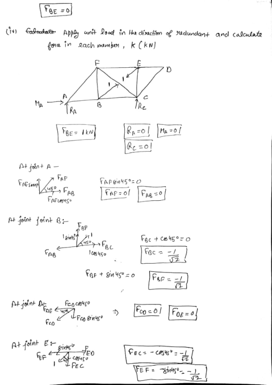
 A symmetric truss system is subjected to a concentrated vertical force P at joint B as shown in Figure Q6. By using energy method, determine the horizontal displacement of joint C. EA is assumed as constant for all members, L is the length of member AB. D A С 450 450 B L Figure Q6
Prob. 1 Obtain the influence line for the vertical reaction at the center support. The span length of each span is L. (...
 Prob. 1 Obtain the influence line for the vertical reaction at the center support. The span length of each span is L. (40 pts.) EI EI Prob. 2 Calculate the reaction at the center support of the beam given in Prob. 1 when a uniform dead load qis applied using the influence line. (20 pts.)
Prob. 1 Obtain the influence line for the vertical reaction at the center support. The span length of each span is L. (40 pts.) EI...
Prob. 1 Obtain the influence line for the vertical reaction at the center support. The span length of each span is L. (40 pts.) EI EI Prob. 2 Calculate the reaction at the center support of the beam given in Prob. 1 when a uniform dead load qis applied using the influence line. (20 pts.)
Prob. 1 Obtain the influence line for the vertical reaction at the center support. The span length of each span is L. (40 pts.) EI...
Consider the truss subjected to a single point load P = 12 kN downward at point...
 Consider the truss subjected to a single point load P = 12 kN
downward at point C (Figure 1). The members of the truss all have E
= 200 GPa and cross-sectional area 25 cm2.
<ME316 HW9 - Energy Methods Conservation of Energy View Available Hint(s) Learning Goal: To use conservation of energy to calculate the displacement of a point in a truss When a structure is subjected to a single point load and deforms in a linear- elastic fashion,...
Consider the truss subjected to a single point load P = 12 kN
downward at point C (Figure 1). The members of the truss all have E
= 200 GPa and cross-sectional area 25 cm2.
<ME316 HW9 - Energy Methods Conservation of Energy View Available Hint(s) Learning Goal: To use conservation of energy to calculate the displacement of a point in a truss When a structure is subjected to a single point load and deforms in a linear- elastic fashion,...
Shown below is a crank with 5 kN load. Calculate the vertical deflection at the point...
 Shown below is a crank with 5 kN load. Calculate the vertical deflection at the point of the load. The material properties are E = 2003 MPa, G= 80e3 MPa. Show which segment is going through bending and which bending + torsion. (Hint: Total external strain energy = 72 PS) 5 kN Uim= att S m² dx 400 mm с 500 mm UiT J ST² dx 10 mm x 40 mm Section B 40 mm dia.
Use slope-deflection method to analyze the frame shown below. Segments AB and BD of the frame...
 Use slope-deflection method to analyze the frame shown below. Segments AB and BD of the frame have moment of inertia I. Segment BC has moment of inertia 2/. Modulus of elasticity E is constant throughout the frame. The frame is supported by fixed-supports at A and D, and by a roller-support at C. Joint B is rigid. A downward point load of 20 kN is applied at mid-span of AB. Uniformly distributed load of intensity 2 kN/m acting downwards is...
Problem 1 Analyze the truss structure (statically determinate) shown below. The diameter of the c...
 Problem 1 Analyze the truss structure (statically determinate) shown below. The diameter of the circular truss members is 4 cm. The material used has an elastic modulus E-160GPa 1. Calculate the forces in each truss member. 2. Calculate the horizontal and vertical displacements 1 KN of the truss nodes B and C Calculate the margin of safety. Note: Tension members can fail by stress failure and compression members can fail by stress failure or buckling. 3. 1.732 m 2 KN...
 Determine the horizontal deflection at joint E of the truss
shown below by (a) Virtual workmethod (b) Castigliano’s second
theorem
Problem 1. Determine the horizontal deflection at joint E of the truss shown below by a) Virtual work method [13 pts] b) Castigliano's second theorem (13 pts] 6k 6k 6k bo 4k C E 10 ft B |-54t-5-5f-+5ft- EA = constant E = 29,000 ksi A = 6 in.2
Determine the horizontal deflection at joint E of the truss
shown below by (a) Virtual workmethod (b) Castigliano’s second
theorem
Problem 1. Determine the horizontal deflection at joint E of the truss shown below by a) Virtual work method [13 pts] b) Castigliano's second theorem (13 pts] 6k 6k 6k bo 4k C E 10 ft B |-54t-5-5f-+5ft- EA = constant E = 29,000 ksi A = 6 in.2
 12 kN 144. Determine the vertical deflection at joint 2 and the force in member 4 of the truss in Prob. 14-3. Take A = 0,0015 m- and E = 200 GPa for each member. Page 20
 Problem 4: Shown below is a crank with 5 kN load. Calculate the vertical deflection at the point of the load. The material properties are E = 2003 MPa, G= 80e3 MPa. Show which segment is going through bending and which bending + torsion. (Hint: Total external strain energy = 72 PS) Z 5 kN Y Uim M² dx 400 mm С X ZEI 500 mm UiT aco ST dx 10 mm x 40 mm Section B. 40 mm dia.
 Problem 4: Shown below is a crank with 5 kN load. Calculate the vertical deflection at the point of the load. The material properties are E = 2003 MPa, G= 80e3 MPa. Show which segment is going through bending and which bending + torsion. (Hint: Total external strain energy = 72 PS) Z 5 kN Y Uim M² dx 400 mm С X ZEI 500 mm UiT aco ST dx 10 mm x 40 mm Section B. 40 mm dia.
 A symmetric truss system is subjected to a concentrated vertical force P at joint B as shown in Figure Q6. By using energy method, determine the horizontal displacement of joint C. EA is assumed as constant for all members, L is the length of member AB. D A С 450 450 B L Figure Q6
 Prob. 1 Obtain the influence line for the vertical reaction at the center support. The span length of each span is L. (40 pts.) EI EI Prob. 2 Calculate the reaction at the center support of the beam given in Prob. 1 when a uniform dead load qis applied using the influence line. (20 pts.)
Prob. 1 Obtain the influence line for the vertical reaction at the center support. The span length of each span is L. (40 pts.) EI...
Prob. 1 Obtain the influence line for the vertical reaction at the center support. The span length of each span is L. (40 pts.) EI EI Prob. 2 Calculate the reaction at the center support of the beam given in Prob. 1 when a uniform dead load qis applied using the influence line. (20 pts.)
Prob. 1 Obtain the influence line for the vertical reaction at the center support. The span length of each span is L. (40 pts.) EI...
 Consider the truss subjected to a single point load P = 12 kN
downward at point C (Figure 1). The members of the truss all have E
= 200 GPa and cross-sectional area 25 cm2.
<ME316 HW9 - Energy Methods Conservation of Energy View Available Hint(s) Learning Goal: To use conservation of energy to calculate the displacement of a point in a truss When a structure is subjected to a single point load and deforms in a linear- elastic fashion,...
Consider the truss subjected to a single point load P = 12 kN
downward at point C (Figure 1). The members of the truss all have E
= 200 GPa and cross-sectional area 25 cm2.
<ME316 HW9 - Energy Methods Conservation of Energy View Available Hint(s) Learning Goal: To use conservation of energy to calculate the displacement of a point in a truss When a structure is subjected to a single point load and deforms in a linear- elastic fashion,...
 Shown below is a crank with 5 kN load. Calculate the vertical deflection at the point of the load. The material properties are E = 2003 MPa, G= 80e3 MPa. Show which segment is going through bending and which bending + torsion. (Hint: Total external strain energy = 72 PS) 5 kN Uim= att S m² dx 400 mm с 500 mm UiT J ST² dx 10 mm x 40 mm Section B 40 mm dia.
 Use slope-deflection method to analyze the frame shown below. Segments AB and BD of the frame have moment of inertia I. Segment BC has moment of inertia 2/. Modulus of elasticity E is constant throughout the frame. The frame is supported by fixed-supports at A and D, and by a roller-support at C. Joint B is rigid. A downward point load of 20 kN is applied at mid-span of AB. Uniformly distributed load of intensity 2 kN/m acting downwards is...
 Problem 1 Analyze the truss structure (statically determinate) shown below. The diameter of the circular truss members is 4 cm. The material used has an elastic modulus E-160GPa 1. Calculate the forces in each truss member. 2. Calculate the horizontal and vertical displacements 1 KN of the truss nodes B and C Calculate the margin of safety. Note: Tension members can fail by stress failure and compression members can fail by stress failure or buckling. 3. 1.732 m 2 KN...
Most questions answered within 3 hours.
-
Where is the error in this code sequence?
String s1 = "Hello";
String s2 = "ello";...
asked 11 months ago -
Financial data for Joel de Paris, Inc., for last year
follow:
Joel de Paris, Inc.
Balance...
asked 11 months ago -
Consider this reaction:
Al2(SO4)3 (aq)+ BaCl3
(aq) Al2Cl6 (aq)- +
3BaSO4(s) . What is the...
asked 11 months ago -
Suppose that Savneet is considering increasing her
recent random sample from 20 car rentals to 40...
asked 11 months ago -
Trucks arrive at an unloading terminal at an average rate of 120
per hour.
Trucks arrive...
asked 11 months ago -
Why are methanol and ethanol completely soluble in water while
octanol is not very little soluble....
asked 11 months ago -
A facilities manager at a university reads in a research report
that the mean amount of...
asked 11 months ago -
When the CuSO4 is rehydrated by adding water to the anhydrous
compound, is this an endothermic...
asked 11 months ago -
A ray of sunlight is passing from diamond into crown glass; the
angle of incidence is...
asked 11 months ago -
A block of mass 0.249 kg is placed on top of a light, vertical
spring of...
asked 11 months ago -
how do the kidneys compensate in the presences of acidosis
a) trigger hyperventilate
b) reserve acid...
asked 11 months ago -
Question 501 pts
The rental rate of capital to the firm increases. Which of the
following...
asked 11 months ago