
Homework Answers

Add Answer to:
1.41 Link AB is to be made of a steel for which the ultimate normal stress...
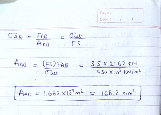
8.33 Link AB is to be made of a steel for which the ultimate normal is...
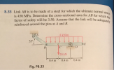 8.33 Link AB is to be made of a steel for which the ultimate normal is 450 MPa. Determine the cross-sectional area for AB for which factor of safety will be 3.50. Assume that the link will be adega reinforced around the pins at A and B. will be adequately 8 kN/m 35° OE 20 kN 0.4 m 0.4 m 0.4 m Fig. P8.33
1.51 In the steel structure shown, a 6-mm-diameter pin is used at C and 10-mm-diameter pins...
 1.51 In the steel structure shown, a 6-mm-diameter pin is used at C and 10-mm-diameter pins are used at B and D. The ultimate shearing stress is 150 MPa at all connections, and the ultimate normal stress is 400 MPa in link BD. Knowing that a factor of safety of 3.0 is desired, determine the largest load P that can be applied at A. Note that ink BD is not reinforced around the pin holes Front view 18 mm Side...
In the steel structure shown, a 6-mm-diameter pin is used at C and 10-mm-diameter pins are...
 In the steel structure shown, a 6-mm-diameter pin is used at C and 10-mm-diameter pins are used at B and D. The ultimate shearing stress is 159 MPa at all connections, and the ultimate normal stress is 400 MPa in link BD. Knowing that a factor of safety of 3.0 is desired, determine the largest load P that can be applied at A. Note that link BD is not reinforced around the pin holes. (Round the final answer to three...
1.52 Solve Prob. 1.51, assuming that the structure has been redesigned to use 16-in.-diameter pins at...
 1.52 Solve Prob. 1.51, assuming that the structure has been redesigned to use 16-in.-diameter pins at A and C as well as at B and that no other changes have been made. A in. 8 in. B C 4 in. 6 in. Fig.P1.51 1.51 Link AC is made of a steel with a 65-ksi ultimate normal stress and has a 2-in. uniform rectangular cross section. It is connected to a support at A and to member BCD at C by-in.-diameter...
Problem 4 (3pts) The beam AB is supported by a single-shear pin connection at joint A...
 Problem 4 (3pts) The beam AB is supported by a single-shear pin connection at joint A and by a double-shear connection to member (1) at joint B. Member (1) is connected to the support at C with a double-shear pin connection. Member (1) has a cross-sectional area of 100 mm and a yield strength of 340 MPa. The pins at A, B, and C each have a diameter of 12 mm, and an ultimate shear strength of 270 MPa. Specifications...
The rods AB and CD are made of steel having a failure tensile stress of O...
 The rods AB and CD are made of steel having a failure tensile stress of O fail = 510 MPa. Using a factor of safety of F.S. = 1.75 for tension, determine their smallest diameter so that they can support the load shown. The beam is assumed to be pin connected at A and C. В. D 6 kN 5 kN 4 kN A C 4 2 m ----2m- -3 m -3 m Figure: 07_PROB_076
5.3 m 7.5 m B D (1) 60 8 m 3.4 m P The rigid T...
 5.3 m 7.5 m B D (1) 60 8 m 3.4 m P The rigid T shape ABD is supported by an elastic rod BC (with a 35 mm diameter). Pin A (30 diameter) is in single shear. mm Double shear pins B and C are 24 mm diameter. Rod BC has a yield stress of 250 MPa and all pins have a ultimate shear stress of 330 MPa. Take P 50 kN and determine: Normal stress in BC 1...
Question 2: (15 marks) Bracket ABC has loads applied as identified in Figure 2. A steel control r...
 please label with detailed steps ! thank you
Question 2: (15 marks) Bracket ABC has loads applied as identified in Figure 2. A steel control rod A with ultimate normal stress of 600 MPa is attached to point B. At point C the steel pivot pin has an ultimate shearing stress of 350 MPa. Assuming a factor of safety of 3.3 determine: (i) The minimum acceptable diameter of the control rod AB (ii) The minimum acceptable diameter of the pivot...
please label with detailed steps ! thank you
Question 2: (15 marks) Bracket ABC has loads applied as identified in Figure 2. A steel control rod A with ultimate normal stress of 600 MPa is attached to point B. At point C the steel pivot pin has an ultimate shearing stress of 350 MPa. Assuming a factor of safety of 3.3 determine: (i) The minimum acceptable diameter of the control rod AB (ii) The minimum acceptable diameter of the pivot...
show every step 2·The link BC is 1-6mm thick (into the page) and has width, w(that...
 show every step
2·The link BC is 1-6mm thick (into the page) and has width, w(that is, the cross section of the link is t by w). The link is made of steel, with an ultimate strength of 450 MPa in tension. What should the width of the link be if 40 480mm the structure is designed to support a load of P- 20 kN with a factor of safety equal to 3. (Hint: BC is a two-force member.) Ans:...
show every step
2·The link BC is 1-6mm thick (into the page) and has width, w(that is, the cross section of the link is t by w). The link is made of steel, with an ultimate strength of 450 MPa in tension. What should the width of the link be if 40 480mm the structure is designed to support a load of P- 20 kN with a factor of safety equal to 3. (Hint: BC is a two-force member.) Ans:...
 8.33 Link AB is to be made of a steel for which the ultimate normal is 450 MPa. Determine the cross-sectional area for AB for which factor of safety will be 3.50. Assume that the link will be adega reinforced around the pins at A and B. will be adequately 8 kN/m 35° OE 20 kN 0.4 m 0.4 m 0.4 m Fig. P8.33
 1.51 In the steel structure shown, a 6-mm-diameter pin is used at C and 10-mm-diameter pins are used at B and D. The ultimate shearing stress is 150 MPa at all connections, and the ultimate normal stress is 400 MPa in link BD. Knowing that a factor of safety of 3.0 is desired, determine the largest load P that can be applied at A. Note that ink BD is not reinforced around the pin holes Front view 18 mm Side...
 In the steel structure shown, a 6-mm-diameter pin is used at C and 10-mm-diameter pins are used at B and D. The ultimate shearing stress is 159 MPa at all connections, and the ultimate normal stress is 400 MPa in link BD. Knowing that a factor of safety of 3.0 is desired, determine the largest load P that can be applied at A. Note that link BD is not reinforced around the pin holes. (Round the final answer to three...
 1.52 Solve Prob. 1.51, assuming that the structure has been redesigned to use 16-in.-diameter pins at A and C as well as at B and that no other changes have been made. A in. 8 in. B C 4 in. 6 in. Fig.P1.51 1.51 Link AC is made of a steel with a 65-ksi ultimate normal stress and has a 2-in. uniform rectangular cross section. It is connected to a support at A and to member BCD at C by-in.-diameter...
 Problem 4 (3pts) The beam AB is supported by a single-shear pin connection at joint A and by a double-shear connection to member (1) at joint B. Member (1) is connected to the support at C with a double-shear pin connection. Member (1) has a cross-sectional area of 100 mm and a yield strength of 340 MPa. The pins at A, B, and C each have a diameter of 12 mm, and an ultimate shear strength of 270 MPa. Specifications...
 The rods AB and CD are made of steel having a failure tensile stress of O fail = 510 MPa. Using a factor of safety of F.S. = 1.75 for tension, determine their smallest diameter so that they can support the load shown. The beam is assumed to be pin connected at A and C. В. D 6 kN 5 kN 4 kN A C 4 2 m ----2m- -3 m -3 m Figure: 07_PROB_076
 5.3 m 7.5 m B D (1) 60 8 m 3.4 m P The rigid T shape ABD is supported by an elastic rod BC (with a 35 mm diameter). Pin A (30 diameter) is in single shear. mm Double shear pins B and C are 24 mm diameter. Rod BC has a yield stress of 250 MPa and all pins have a ultimate shear stress of 330 MPa. Take P 50 kN and determine: Normal stress in BC 1...
 please label with detailed steps ! thank you
Question 2: (15 marks) Bracket ABC has loads applied as identified in Figure 2. A steel control rod A with ultimate normal stress of 600 MPa is attached to point B. At point C the steel pivot pin has an ultimate shearing stress of 350 MPa. Assuming a factor of safety of 3.3 determine: (i) The minimum acceptable diameter of the control rod AB (ii) The minimum acceptable diameter of the pivot...
please label with detailed steps ! thank you
Question 2: (15 marks) Bracket ABC has loads applied as identified in Figure 2. A steel control rod A with ultimate normal stress of 600 MPa is attached to point B. At point C the steel pivot pin has an ultimate shearing stress of 350 MPa. Assuming a factor of safety of 3.3 determine: (i) The minimum acceptable diameter of the control rod AB (ii) The minimum acceptable diameter of the pivot...
 show every step
2·The link BC is 1-6mm thick (into the page) and has width, w(that is, the cross section of the link is t by w). The link is made of steel, with an ultimate strength of 450 MPa in tension. What should the width of the link be if 40 480mm the structure is designed to support a load of P- 20 kN with a factor of safety equal to 3. (Hint: BC is a two-force member.) Ans:...
show every step
2·The link BC is 1-6mm thick (into the page) and has width, w(that is, the cross section of the link is t by w). The link is made of steel, with an ultimate strength of 450 MPa in tension. What should the width of the link be if 40 480mm the structure is designed to support a load of P- 20 kN with a factor of safety equal to 3. (Hint: BC is a two-force member.) Ans:...
Most questions answered within 3 hours.
-
Where is the error in this code sequence?
String s1 = "Hello";
String s2 = "ello";...
asked 11 months ago -
Financial data for Joel de Paris, Inc., for last year
follow:
Joel de Paris, Inc.
Balance...
asked 11 months ago -
Consider this reaction:
Al2(SO4)3 (aq)+ BaCl3
(aq) Al2Cl6 (aq)- +
3BaSO4(s) . What is the...
asked 11 months ago -
Suppose that Savneet is considering increasing her
recent random sample from 20 car rentals to 40...
asked 11 months ago -
Trucks arrive at an unloading terminal at an average rate of 120
per hour.
Trucks arrive...
asked 11 months ago -
Why are methanol and ethanol completely soluble in water while
octanol is not very little soluble....
asked 11 months ago -
A facilities manager at a university reads in a research report
that the mean amount of...
asked 11 months ago -
When the CuSO4 is rehydrated by adding water to the anhydrous
compound, is this an endothermic...
asked 11 months ago -
A ray of sunlight is passing from diamond into crown glass; the
angle of incidence is...
asked 11 months ago -
A block of mass 0.249 kg is placed on top of a light, vertical
spring of...
asked 11 months ago -
how do the kidneys compensate in the presences of acidosis
a) trigger hyperventilate
b) reserve acid...
asked 11 months ago -
Question 501 pts
The rental rate of capital to the firm increases. Which of the
following...
asked 11 months ago