A)
Draw the shear diagram for the beam.
Begin by placing vertical lines. Place the appropriate function between the vertical lines, ensuring the endpoints have the correct values. NOTE - You should not draw an “extra” vertical line at the location of applied moment.

B)
Draw the moment diagram for the beam.
Begin by placing vertical lines. Then click on "add segment" button to add functions between the lines. NOTE - The curve you choose from the drop-down is only a pictorial representation of a real quadratic/cubic curve. The equation of this curve is not mathematically equivalent to the correct answer. Consequently, slopes at discontinuities and intercepts with the x-axis (if any) are not accurate.

Homework Answers
Equilibrium of a rigid body:
An object is said to be in equilibrium when the sum of external forces and couples are zero.
For a rigid body to be in equilibrium in three dimensions, the sum of external forces acting along  ,
,  and
and  directions have to zero.
For a rigid body to be in equilibrium in three dimensions, the sum of external couples about any point should be zero.
Normal force:
It is the force component acting perpendicular to the contact surface or the cross sectional area of a body.
Shear force:
When force acting on a body pushes two parts of the body in opposite direction then the force is referred as shear force. Shear force on an object acts normal to its cross section.
Bending moment:
It is the degree of bending caused on the beam when an arbitrary load acts on it. Usually moment is said to prevail on a beam or structure that is acted upon by a perpendicular force triggering rotation.
Uniformly distributed load:
It refers to the load that is laid over a particular span of the beam at constant rate. The load that has constant intensity over its span on the beam is referred as uniformly distributed load.
Sign convention of force:
The forces acting towards right side are considered as positive and the forces acting towards left side are considered as negative.
Consider the inclined force  acting at the end
  of the rod AB as shown in Figure (1).
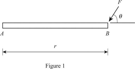
The horizontal component  of force is expressed as follows:

Here, magnitude of the force is  and the angle made by the force with the horizontal axis is
 .
.
The vertical component  of force is expressed as follows:

Write the expression for calculating moment  about point
  .
.

Here, magnitude of the force is  and its perpendicular distance is
  .
.
Write the equilibrium condition for forces along the  -axis.

Here, the sum of forces along x-direction is  .
.
Write the equilibrium condition for forces along the  -axis.

Here, the sum of forces along y-direction is  .
.
Write the relation for equilibrium of moments.

Here, the sum of moments about any point is  .
.
Consider the uniformly distributed load of constant intensity  as shown in Figure (2).

Write the expression for concentrated load  equivalent to the uniformly distributed load.

Here, magnitude of the uniformly distributed load is  and its span is
  .
.
Draw the free body diagram of the beam as shown in the Figure (3).

Apply equilibrium of moments about point  .
.

Apply equilibrium condition for forces along the  direction.

Substitute  for
for  .
.

Apply equilibrium condition for forces along the x direction.

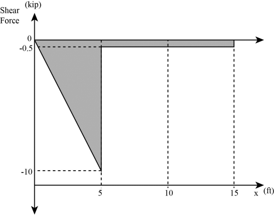
Calculate shear force at point 
 .
.

Calculate shear force at point 
 .
.

Calculate shear force at point 
 .
.

Calculate shear force at point 
 .
.

Calculate the bending moment at point 
 .
.

Calculate the bending moment at point 
 .
.

Substitute  for
for  .
.

Calculate the bending moment at point 
 .
.

Substitute for and  for
for 

The shear force for the beam is

Add Answer to:
A)
Draw the shear diagram for the beam.
Begin by placing vertical lines. Place the appropriate...
Draw the shear diagram for the beam. Begin by placing vertical lines. Place the appropriate function...
 Draw the shear diagram for the beam.
Begin by placing vertical lines. Place the appropriate
function between the vertical lines, ensuring the endpoints have
the correct values.
Draw the moment diagram for the beam.
Begin by placing vertical lines. NOTE - The curve you
choose from the drop-down is only a pictorial representation of a
real quadratic/cubic curve. The equation of this curve is not
mathematically equivalent to the correct answer. Consequently,
slopes at discontinuities and intercepts with the x-axis...
Draw the shear diagram for the beam.
Begin by placing vertical lines. Place the appropriate
function between the vertical lines, ensuring the endpoints have
the correct values.
Draw the moment diagram for the beam.
Begin by placing vertical lines. NOTE - The curve you
choose from the drop-down is only a pictorial representation of a
real quadratic/cubic curve. The equation of this curve is not
mathematically equivalent to the correct answer. Consequently,
slopes at discontinuities and intercepts with the x-axis...
Part A Draw the shear diagram for the beam Begin by placing vertical lines. Place the...
 Part A Draw the shear diagram for the beam Begin by placing vertical lines. Place the appropriate function between the vertical lines, ensuring the endpoints have the correct values. +add vertical line off U reset ? help delete add segment ? 10 kip 8 kip 2 kip/ft 40 kip ft 6 ft 4 ft
Draw the moment diagram for the beam. Begin by placing the lines of discontinuity. Place the...
 Draw the moment diagram for the beam. Begin by placing the lines of discontinuity. Place the appropriate function between the lines of discontinuity, ensuring the endpoints have the correct values Note-Make sure you place only one vertical line at places that require a vertical line. If you inadvertently place two vertical lines at the same place, it will appear visually correct because the lines overlap, but the system will mark it wrong. add vertical line off delete +add segment ?reset...
Part A Draw the shear diagram for the beam. Follow the sign convention. (Figure 1) Click...
 Part A
Draw the shear diagram for the beam. Follow the sign convention.
(Figure 1)
Click on "add vertical line off" to add discontinuity lines.
Then click on "add segment" button to add functions between the
lines.
Note 1 - You should not draw an "extra" discontinuity line at the
point where the curve passes the x-axis.
Note 2 - Be sure to indicate the correct types of the functions
between the lines, e.g. if in your answer the type...
Part A
Draw the shear diagram for the beam. Follow the sign convention.
(Figure 1)
Click on "add vertical line off" to add discontinuity lines.
Then click on "add segment" button to add functions between the
lines.
Note 1 - You should not draw an "extra" discontinuity line at the
point where the curve passes the x-axis.
Note 2 - Be sure to indicate the correct types of the functions
between the lines, e.g. if in your answer the type...
Part D - Draw the Shear Diagram Draw the shear diagram for this beam. Begin by...
 Part D - Draw the Shear Diagram
Draw the shear diagram for this beam.
Begin by placing the lines of discontinuity. Place the appropriate
function between the lines of discontinuity, ensuring the endpoints
have the correct values.
Draw the Shear Diagram Draw the shear diagram for this beam. Begin by placing the lines of discontinuity. Place the appropriate function between the lines of discontinuity, ensuring the endpoints have the correct values.
Part D - Draw the Shear Diagram
Draw the shear diagram for this beam.
Begin by placing the lines of discontinuity. Place the appropriate
function between the lines of discontinuity, ensuring the endpoints
have the correct values.
Draw the Shear Diagram Draw the shear diagram for this beam. Begin by placing the lines of discontinuity. Place the appropriate function between the lines of discontinuity, ensuring the endpoints have the correct values.
Part A Draw the shear diagram for the beam. Follow the sign convention. (Figure 1) Click on "add vertical line off" to add discontinuity lines. Then click on "add segment button to add fu...
 Part A Draw the shear diagram for the beam. Follow the sign convention. (Figure 1) Click on "add vertical line off" to add discontinuity lines. Then click on "add segment button to add functions between the lines. Note 1- You should not draw an "extra" discontinuity line at the point where the curve passes the x-axis. Note 2-Be sure to indicate the correct types of the functions between the lines, e.g. if in your answer the type of a function...
Part A Draw the shear diagram for the beam Click on "add discontinuity" to add discontinuity...
 Part A Draw the shear diagram for the beam Click on "add discontinuity" to add discontinuity lines. Then click on "add segment" button to add functions between the lines. NOTE 1 The curve you choose from the drop-down is only a pictorial representation of a real quadratic/cubic curve. The equation of this curve is not mathematically equivalent to the correct answer. Consequently, slopes at discontinuities and intercepts with the x-axis (if any) are not accurate. NOTE 2 You should not...
draw the shear and moment diagram, Part A Draw the shear diagram for the beam Follow...
 draw the shear and moment diagram,
Part A Draw the shear diagram for the beam Follow the sign convention Click on "add vertical line off to add discontinuity lines. Then click on "add segment" button to add functions between the lines. Note 1 Make sure you place only one vertical line at places that require a vertical line. If you inadvertently place two vertical lines at the same place, it will appear con it wrong Note 2 The curve you...
draw the shear and moment diagram,
Part A Draw the shear diagram for the beam Follow the sign convention Click on "add vertical line off to add discontinuity lines. Then click on "add segment" button to add functions between the lines. Note 1 Make sure you place only one vertical line at places that require a vertical line. If you inadvertently place two vertical lines at the same place, it will appear con it wrong Note 2 The curve you...
Using the differential and integral relations between the load and the shear, draw the shear diagram...
 Using the differential and integral relations between the load and the shear, draw the shear diagram for this beam. Begin by placing the lines of discontinuity. Place the appropriate function between the lines of discontinuity, ensuring the endpoints have the correct values. Note - Make sure you place only one vertical line at places that require a vertical line. If you inadvertently place 2 vertical lines at the same place, it will appear correct visually because the lines overlap, but...
PART A Draw the shear diagram for the beam. Follow the sign convention. (Figure 1) Click on "add vertical line off" to add discontinuity lines. Then click on "add segment" button to a...
 PART A
Draw the shear diagram for the beam. Follow the sign convention.
(Figure 1)
Click on "add vertical line off" to add discontinuity lines.
Then click on "add segment" button to add functions between the
lines.
Note 1 - You should not draw an "extra" discontinuity line at the
point where the curve passes the x-axis.
Note 2 - The curve you choose from the drop-down is only a
pictorial representation of a real quadratic/cubic curve. The
equation of...
PART A
Draw the shear diagram for the beam. Follow the sign convention.
(Figure 1)
Click on "add vertical line off" to add discontinuity lines.
Then click on "add segment" button to add functions between the
lines.
Note 1 - You should not draw an "extra" discontinuity line at the
point where the curve passes the x-axis.
Note 2 - The curve you choose from the drop-down is only a
pictorial representation of a real quadratic/cubic curve. The
equation of...
 Draw the shear diagram for the beam.
Begin by placing vertical lines. Place the appropriate
function between the vertical lines, ensuring the endpoints have
the correct values.
Draw the moment diagram for the beam.
Begin by placing vertical lines. NOTE - The curve you
choose from the drop-down is only a pictorial representation of a
real quadratic/cubic curve. The equation of this curve is not
mathematically equivalent to the correct answer. Consequently,
slopes at discontinuities and intercepts with the x-axis...
Draw the shear diagram for the beam.
Begin by placing vertical lines. Place the appropriate
function between the vertical lines, ensuring the endpoints have
the correct values.
Draw the moment diagram for the beam.
Begin by placing vertical lines. NOTE - The curve you
choose from the drop-down is only a pictorial representation of a
real quadratic/cubic curve. The equation of this curve is not
mathematically equivalent to the correct answer. Consequently,
slopes at discontinuities and intercepts with the x-axis...
 Part A Draw the shear diagram for the beam Begin by placing vertical lines. Place the appropriate function between the vertical lines, ensuring the endpoints have the correct values. +add vertical line off U reset ? help delete add segment ? 10 kip 8 kip 2 kip/ft 40 kip ft 6 ft 4 ft
 Draw the moment diagram for the beam. Begin by placing the lines of discontinuity. Place the appropriate function between the lines of discontinuity, ensuring the endpoints have the correct values Note-Make sure you place only one vertical line at places that require a vertical line. If you inadvertently place two vertical lines at the same place, it will appear visually correct because the lines overlap, but the system will mark it wrong. add vertical line off delete +add segment ?reset...
 Part A
Draw the shear diagram for the beam. Follow the sign convention.
(Figure 1)
Click on "add vertical line off" to add discontinuity lines.
Then click on "add segment" button to add functions between the
lines.
Note 1 - You should not draw an "extra" discontinuity line at the
point where the curve passes the x-axis.
Note 2 - Be sure to indicate the correct types of the functions
between the lines, e.g. if in your answer the type...
Part A
Draw the shear diagram for the beam. Follow the sign convention.
(Figure 1)
Click on "add vertical line off" to add discontinuity lines.
Then click on "add segment" button to add functions between the
lines.
Note 1 - You should not draw an "extra" discontinuity line at the
point where the curve passes the x-axis.
Note 2 - Be sure to indicate the correct types of the functions
between the lines, e.g. if in your answer the type...
 Part D - Draw the Shear Diagram
Draw the shear diagram for this beam.
Begin by placing the lines of discontinuity. Place the appropriate
function between the lines of discontinuity, ensuring the endpoints
have the correct values.
Draw the Shear Diagram Draw the shear diagram for this beam. Begin by placing the lines of discontinuity. Place the appropriate function between the lines of discontinuity, ensuring the endpoints have the correct values.
Part D - Draw the Shear Diagram
Draw the shear diagram for this beam.
Begin by placing the lines of discontinuity. Place the appropriate
function between the lines of discontinuity, ensuring the endpoints
have the correct values.
Draw the Shear Diagram Draw the shear diagram for this beam. Begin by placing the lines of discontinuity. Place the appropriate function between the lines of discontinuity, ensuring the endpoints have the correct values.
 Part A Draw the shear diagram for the beam. Follow the sign convention. (Figure 1) Click on "add vertical line off" to add discontinuity lines. Then click on "add segment button to add functions between the lines. Note 1- You should not draw an "extra" discontinuity line at the point where the curve passes the x-axis. Note 2-Be sure to indicate the correct types of the functions between the lines, e.g. if in your answer the type of a function...
 Part A Draw the shear diagram for the beam Click on "add discontinuity" to add discontinuity lines. Then click on "add segment" button to add functions between the lines. NOTE 1 The curve you choose from the drop-down is only a pictorial representation of a real quadratic/cubic curve. The equation of this curve is not mathematically equivalent to the correct answer. Consequently, slopes at discontinuities and intercepts with the x-axis (if any) are not accurate. NOTE 2 You should not...
 draw the shear and moment diagram,
Part A Draw the shear diagram for the beam Follow the sign convention Click on "add vertical line off to add discontinuity lines. Then click on "add segment" button to add functions between the lines. Note 1 Make sure you place only one vertical line at places that require a vertical line. If you inadvertently place two vertical lines at the same place, it will appear con it wrong Note 2 The curve you...
draw the shear and moment diagram,
Part A Draw the shear diagram for the beam Follow the sign convention Click on "add vertical line off to add discontinuity lines. Then click on "add segment" button to add functions between the lines. Note 1 Make sure you place only one vertical line at places that require a vertical line. If you inadvertently place two vertical lines at the same place, it will appear con it wrong Note 2 The curve you...
 Using the differential and integral relations between the load and the shear, draw the shear diagram for this beam. Begin by placing the lines of discontinuity. Place the appropriate function between the lines of discontinuity, ensuring the endpoints have the correct values. Note - Make sure you place only one vertical line at places that require a vertical line. If you inadvertently place 2 vertical lines at the same place, it will appear correct visually because the lines overlap, but...
 PART A
Draw the shear diagram for the beam. Follow the sign convention.
(Figure 1)
Click on "add vertical line off" to add discontinuity lines.
Then click on "add segment" button to add functions between the
lines.
Note 1 - You should not draw an "extra" discontinuity line at the
point where the curve passes the x-axis.
Note 2 - The curve you choose from the drop-down is only a
pictorial representation of a real quadratic/cubic curve. The
equation of...
PART A
Draw the shear diagram for the beam. Follow the sign convention.
(Figure 1)
Click on "add vertical line off" to add discontinuity lines.
Then click on "add segment" button to add functions between the
lines.
Note 1 - You should not draw an "extra" discontinuity line at the
point where the curve passes the x-axis.
Note 2 - The curve you choose from the drop-down is only a
pictorial representation of a real quadratic/cubic curve. The
equation of...
Most questions answered within 3 hours.
-
Where is the error in this code sequence?
String s1 = "Hello";
String s2 = "ello";...
asked 10 months ago -
Financial data for Joel de Paris, Inc., for last year
follow:
Joel de Paris, Inc.
Balance...
asked 10 months ago -
Consider this reaction:
Al2(SO4)3 (aq)+ BaCl3
(aq) Al2Cl6 (aq)- +
3BaSO4(s) . What is the...
asked 10 months ago -
Suppose that Savneet is considering increasing her
recent random sample from 20 car rentals to 40...
asked 10 months ago -
Trucks arrive at an unloading terminal at an average rate of 120
per hour.
Trucks arrive...
asked 10 months ago -
Why are methanol and ethanol completely soluble in water while
octanol is not very little soluble....
asked 10 months ago -
A facilities manager at a university reads in a research report
that the mean amount of...
asked 10 months ago -
When the CuSO4 is rehydrated by adding water to the anhydrous
compound, is this an endothermic...
asked 10 months ago -
A ray of sunlight is passing from diamond into crown glass; the
angle of incidence is...
asked 10 months ago -
A block of mass 0.249 kg is placed on top of a light, vertical
spring of...
asked 10 months ago -
how do the kidneys compensate in the presences of acidosis
a) trigger hyperventilate
b) reserve acid...
asked 10 months ago -
Question 501 pts
The rental rate of capital to the firm increases. Which of the
following...
asked 10 months ago