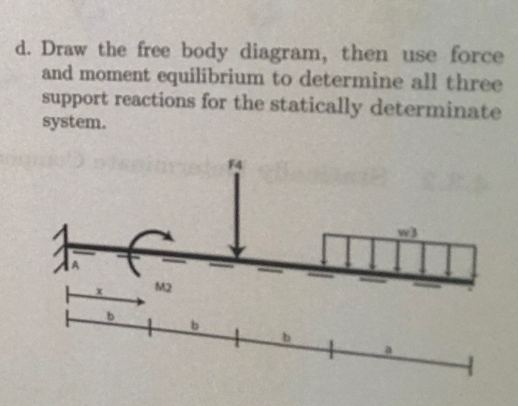
Distance [Length]
a = 9
b = 6
c = 6
d = 15
Concentrated Forces [Force]
F1 = 80
F2 = 60
F3 = 108
F4 = 110
Distributed Forces [Force/Distance]
w1 = 12
w2 = 12
w3 = 8
w4 = 20
Concentrated Moments [Force * Distance]
M1 = 680
M2 = 570
M3 = 900
M4 = 1320
Angles [Degree]
alpha = 21
beta = 10.6666666667
gamma = 49
delta = 46.6666666667
Spring Constants [Force/Length]
k1 = 1625
k2 = 16000
k3 = 3450
k4 = 11700
Homework Answers

P=10 kN A cantilever beam is subiected to a concentrated force P, a uniformly distributed load...
 P=10 kN A cantilever beam is subiected to a concentrated force P, a uniformly distributed load w and a moment MI shown in the figure. Neglect the weight of the beam. (a) Draw the free body diagram for the beam showing all the 2 m reactions, replacing the support M.-2 kNm by the reaction forces/moments. (b) Use the equations of equilibrium to find the reaction forces/moments at R (c) Give the expression for the shear force, V- V(x), and the...
Question 4. A) Describe the conditions required for any three forces to be in equilibrium. [2...
 Question 4. A) Describe the conditions required for any three forces to be in equilibrium. [2 marks] B) A force P = 5000N is applied at the centre C of the beam AB of length 5m as shown in the fig 4B. Draw free body diagram for the beam and find the reactions at the hinge and the roller support. [8 marks] P= 5000 N А C 30° B 2.5 m 2.5 m Fig. 4B. The loaded beam and the...
H a) Calculate the reactions forces at the supports A and D. b) Use Macaulay notation...
 H a) Calculate the reactions forces at the supports A and D. b) Use Macaulay notation to find equations for the shear force and the bending moment (M) c) Draw the shear force diagram, either by inspection or by using equations from part b). d) Draw the bending moment diagram, either by inspection or by using equations from part b) e) Determine the maximum value of the bending moment (M), and where on the beam it occurs. The length of...
A child swings a bat at a tee, missing the ball on top and hitting theF...
 A child swings a bat at a tee, missing the ball on top and hitting theF tee instead. Draw a free-body diagram of the tee and use it to find the e reaction forces and moment at the base of the tee. Model the base of the tee as a fixed support. Assume that the magnitude of the force F- 300 N, that it strikes the tee at a distance d-1 m from the support at the ground, and that...
Section 1.3 Statics Review Example 1-1 FIGURE 1-6 Plane truss model 2P - c = 80°...
 Section 1.3 Statics Review Example 1-1 FIGURE 1-6 Plane truss model 2P - c = 80° a As KOA = 60° - Og = 40° B The plane truss shown in Fig. 1-6 has four joints and five mem- bers. Find support reactions at A and B and then use the methods of joints and sections to find all member forces. Let P = 35 kips and c = 10 ft. Solution: Use the following four-step problem-solving approach. 1. Conceptualize...
(b (b d o р There are several forces acting on each sphere: gravity is pulling...
 (b (b d o р There are several forces acting on each sphere: gravity is pulling it down, the electric field is pushing it away from the other sphere, and the tension on the string is keeping it aloft. The spheres are not accelerating, which means that the forces are in equilibrium. To help you understand how the forces are related, we are providing you with the free body diagram for the sphere on the right. Fr is the force...
Three identical masses (A, B, and C) are placed at the corners of a square as...
 Three identical masses (A, B, and C) are placed at the corners
of a square as shown; the distance
between consecutive corners is 0.30 m. These masses are
connected together by three identical
springs; each spring has a spring constant of k = 5:0 N/m. The
equilibrium length of each spring
is 0.20 m.
1. Three identical masses (A, B, and C) are placed at the corners of a square as shown; the distance between consecutive corners is 0.30 m....
Three identical masses (A, B, and C) are placed at the corners
of a square as shown; the distance
between consecutive corners is 0.30 m. These masses are
connected together by three identical
springs; each spring has a spring constant of k = 5:0 N/m. The
equilibrium length of each spring
is 0.20 m.
1. Three identical masses (A, B, and C) are placed at the corners of a square as shown; the distance between consecutive corners is 0.30 m....
(III) A uniform rod AB of length 5.0 m and mass M = 3.8 kg is...
 (III) A uniform rod AB of length 5.0 m and mass M = 3.8 kg is hinged at A and held in equilibrium by a light cord, as shown in Fig. 9-67. A load W = 22 N hangs from the rod at a distance d so that the tension in the cord is 85 N. (a) Draw a free-body diagram for the rod. (b) Determine the vertical and horizontal forces on the rod exerted by the hinge. (c) Determine...
Matching A. Metric unit of force B. Unit of work in the metric system C. Metric...
Matching A. Metric unit of force B. Unit of work in the metric system C. Metric unit of power D. Unit of work in English system E. Unit of pressure in metric system named after the scientist Torricelli F. Mass per unit volume G. The force that is dependent on the masses and distance between them H. A unit of angular measure I. The acceleration of and object traveling with a circular motion J. The displacement of an object as...
PLEASE HELP ME INPUT THIS INTO MATLAB, this is solutions manual for DESIGN of MACHINERY 5th...
 PLEASE HELP ME INPUT THIS INTO MATLAB, this is
solutions manual for DESIGN of MACHINERY 5th Edition number
11-12
PROBLEM 11-12 Statement: Figure P11-5b shows a fourbar linkage and its dimensions in meters. The steel crank, coupler, and rocker have uniform cross sections of 60 mm diameter. In the instantaneous position shown, the crank 0,4 has a = -10 rad/sec and a = 10 rad/sec2. There is a honizontal force at P of F = 500 N. Find all pin...
PLEASE HELP ME INPUT THIS INTO MATLAB, this is
solutions manual for DESIGN of MACHINERY 5th Edition number
11-12
PROBLEM 11-12 Statement: Figure P11-5b shows a fourbar linkage and its dimensions in meters. The steel crank, coupler, and rocker have uniform cross sections of 60 mm diameter. In the instantaneous position shown, the crank 0,4 has a = -10 rad/sec and a = 10 rad/sec2. There is a honizontal force at P of F = 500 N. Find all pin...
 P=10 kN A cantilever beam is subiected to a concentrated force P, a uniformly distributed load w and a moment MI shown in the figure. Neglect the weight of the beam. (a) Draw the free body diagram for the beam showing all the 2 m reactions, replacing the support M.-2 kNm by the reaction forces/moments. (b) Use the equations of equilibrium to find the reaction forces/moments at R (c) Give the expression for the shear force, V- V(x), and the...
 Question 4. A) Describe the conditions required for any three forces to be in equilibrium. [2 marks] B) A force P = 5000N is applied at the centre C of the beam AB of length 5m as shown in the fig 4B. Draw free body diagram for the beam and find the reactions at the hinge and the roller support. [8 marks] P= 5000 N А C 30° B 2.5 m 2.5 m Fig. 4B. The loaded beam and the...
 H a) Calculate the reactions forces at the supports A and D. b) Use Macaulay notation to find equations for the shear force and the bending moment (M) c) Draw the shear force diagram, either by inspection or by using equations from part b). d) Draw the bending moment diagram, either by inspection or by using equations from part b) e) Determine the maximum value of the bending moment (M), and where on the beam it occurs. The length of...
 A child swings a bat at a tee, missing the ball on top and hitting theF tee instead. Draw a free-body diagram of the tee and use it to find the e reaction forces and moment at the base of the tee. Model the base of the tee as a fixed support. Assume that the magnitude of the force F- 300 N, that it strikes the tee at a distance d-1 m from the support at the ground, and that...
 Section 1.3 Statics Review Example 1-1 FIGURE 1-6 Plane truss model 2P - c = 80° a As KOA = 60° - Og = 40° B The plane truss shown in Fig. 1-6 has four joints and five mem- bers. Find support reactions at A and B and then use the methods of joints and sections to find all member forces. Let P = 35 kips and c = 10 ft. Solution: Use the following four-step problem-solving approach. 1. Conceptualize...
 (b (b d o р There are several forces acting on each sphere: gravity is pulling it down, the electric field is pushing it away from the other sphere, and the tension on the string is keeping it aloft. The spheres are not accelerating, which means that the forces are in equilibrium. To help you understand how the forces are related, we are providing you with the free body diagram for the sphere on the right. Fr is the force...
 Three identical masses (A, B, and C) are placed at the corners
of a square as shown; the distance
between consecutive corners is 0.30 m. These masses are
connected together by three identical
springs; each spring has a spring constant of k = 5:0 N/m. The
equilibrium length of each spring
is 0.20 m.
1. Three identical masses (A, B, and C) are placed at the corners of a square as shown; the distance between consecutive corners is 0.30 m....
Three identical masses (A, B, and C) are placed at the corners
of a square as shown; the distance
between consecutive corners is 0.30 m. These masses are
connected together by three identical
springs; each spring has a spring constant of k = 5:0 N/m. The
equilibrium length of each spring
is 0.20 m.
1. Three identical masses (A, B, and C) are placed at the corners of a square as shown; the distance between consecutive corners is 0.30 m....
 (III) A uniform rod AB of length 5.0 m and mass M = 3.8 kg is hinged at A and held in equilibrium by a light cord, as shown in Fig. 9-67. A load W = 22 N hangs from the rod at a distance d so that the tension in the cord is 85 N. (a) Draw a free-body diagram for the rod. (b) Determine the vertical and horizontal forces on the rod exerted by the hinge. (c) Determine...
 PLEASE HELP ME INPUT THIS INTO MATLAB, this is
solutions manual for DESIGN of MACHINERY 5th Edition number
11-12
PROBLEM 11-12 Statement: Figure P11-5b shows a fourbar linkage and its dimensions in meters. The steel crank, coupler, and rocker have uniform cross sections of 60 mm diameter. In the instantaneous position shown, the crank 0,4 has a = -10 rad/sec and a = 10 rad/sec2. There is a honizontal force at P of F = 500 N. Find all pin...
PLEASE HELP ME INPUT THIS INTO MATLAB, this is
solutions manual for DESIGN of MACHINERY 5th Edition number
11-12
PROBLEM 11-12 Statement: Figure P11-5b shows a fourbar linkage and its dimensions in meters. The steel crank, coupler, and rocker have uniform cross sections of 60 mm diameter. In the instantaneous position shown, the crank 0,4 has a = -10 rad/sec and a = 10 rad/sec2. There is a honizontal force at P of F = 500 N. Find all pin...
Most questions answered within 3 hours.
-
Where is the error in this code sequence?
String s1 = "Hello";
String s2 = "ello";...
asked 10 months ago -
Financial data for Joel de Paris, Inc., for last year
follow:
Joel de Paris, Inc.
Balance...
asked 10 months ago -
Consider this reaction:
Al2(SO4)3 (aq)+ BaCl3
(aq) Al2Cl6 (aq)- +
3BaSO4(s) . What is the...
asked 10 months ago -
Suppose that Savneet is considering increasing her
recent random sample from 20 car rentals to 40...
asked 10 months ago -
Trucks arrive at an unloading terminal at an average rate of 120
per hour.
Trucks arrive...
asked 10 months ago -
Why are methanol and ethanol completely soluble in water while
octanol is not very little soluble....
asked 10 months ago -
A facilities manager at a university reads in a research report
that the mean amount of...
asked 10 months ago -
When the CuSO4 is rehydrated by adding water to the anhydrous
compound, is this an endothermic...
asked 10 months ago -
A ray of sunlight is passing from diamond into crown glass; the
angle of incidence is...
asked 10 months ago -
A block of mass 0.249 kg is placed on top of a light, vertical
spring of...
asked 10 months ago -
how do the kidneys compensate in the presences of acidosis
a) trigger hyperventilate
b) reserve acid...
asked 10 months ago -
Question 501 pts
The rental rate of capital to the firm increases. Which of the
following...
asked 10 months ago