The beam is subjected to a moment of M = 4.8kip·ft . (Figure 1)
The beam is subjected to a moment of M = 4.8kip·ft . (Figure 1)
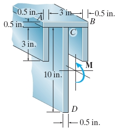
Part A
Determine the maximum tensile bending stress in the beam.
Part B
Determine the maximum compressive bending stress in the beam.
Homework Answers
When loads are applied on a beam, it develops an internal shear force and bending moment which vary from point to point along the axis of the beam. The shear and bending moment functions can be plotted on a graph paper, taking the beam as reference, called shear force and bending moment diagrams.
Bending on the beam also causes tensile and compressive stresses on the beam and these stresses depend on the beam’s geometry.
The bending stress distribution in the cross-section of a beam subjected to bending moment varies linearly from zero at neutral axis to a maximum at a distance farthest from the neutral axis when the beam material is assumed to behave in a linear elastic manner.
Centroid is the mean position of all points in a geometric figure. The summation of the displacements of every point in the geometric figure from the centroid is zero. Centroid of an area is nothing but the centroid of mass. It is the point whose coordinates are the mean of all points in the geometric area.
The formula for calculating the centroid of the cross section is,
Here, the area of each member is and the location of the member’s centroid is .
The formula for calculating the moment of inertia is given by,
Here the base length and height of each member are and respectively.
The formula for bending stress is given by,
Here, the bending moment is M, the moment of inertia is I, and the location of the beam’s outermost fiber from the neutral axis is y.
Draw the diagram of the cross-section.
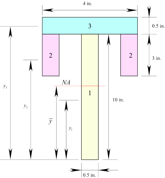
Find the y-coordinate of the neutral axis using the formula,
Find the moment of inertia of section – 1 about the neutral axis.
Find the moment of inertia of section – 2 about the neutral axis.
Find the moment of inertia of section – 3 about the neutral axis.
Calculate the total moment of inertia of the beam.
Find the distance of the bottommost fiber from the neutral axis.
Calculate the bending stress at the bottom most fiber.
Here, is the bending moment.
Substitute for , for , and for .
Find the distance of the uppermost fiber from the neutral axis.
Calculate the bending stress at the bottom most fiber.
Here, is the bending moment.
Substitute for , for , and for .
Ans: Part A
Therefore, the maximum tensile bending stress in the beam is .
Part BTherefore, the maximum compressive bending stress in the beam is .
If the beam, shown in Figure 6, is subjected to an internal moment of 2.5 kNm,...
 If the beam, shown in Figure 6, is subjected to an internal moment of 2.5 kNm, determine the maximum tensile and compressive stress in the beam. Also sketch the bending stress distribution on the cross section.
Determine the maximum tensile and compressive bending stress in the beam if it is subjected to a moment of M = 6 kip-ft.
 Problem 2 - Bending Stress Determine the maximum tensile and compressive bending stress in the beam if it is subjected to a moment of M = 6 kip-ft.
If the beam is subjected to a moment of M = 100 kn-m, determine the bending stress at points A, B, and C.
 If the beam is subjected to a moment of M = 100 kn-m, determine the bending stress at points A, B, and C. Sketch the bending stress distribution on the cross Section. If the beam is made of a material having an allowable tensile and compressive stress of σallow(T) = 125 MPa and σallow(C) = 150 MPa, respectively, determine the maximum moment M that can be applied to the beam.
A beam whose cross-section is shown in the figure is subjected to a bending moment M...
 A beam whose cross-section is shown in the figure is subjected to a bending moment M inclined at 0 = 70° from the z axis. a) Locate the orientation of the neutral axis B and draw this axis on the figure b) Calculate the maximum flexural tensile stress Omax,T and the maximum flexural compressive stress Omax.c in the beam and indicate at which points in the section these occur. M= 2 Nm D e Z 20 mm A B 60...
The beam is subjected to an internal moment of M = 82 kN.m. (Figure 1)
 The beam is subjected to an internal moment of M = 82 kN.m. (Figure 1) Part A Determine the bending stress developed at point A. Part B Determine the bending stress developed at point B. Part C Determine the bending stress developed at point C.
If the beam in figure 3 is subjected to a bending moment of M =20...
 If the beam in figure 3 is subjected to a bending moment of M =
20 kN.m, determine the maximum bending stress in the beam
If the beam in figure 3 is subjected to a bending moment of M =
20 kN.m, determine the maximum bending stress in the beam
Determine the maximum tensile and compressive bending stress in the beam if it is subjected to...
 Determine the maximum tensile and compressive bending stress in the beam if it is subjected to a moment of M=4 kip. ft
Problem 6.54 The builtl up beam in (Figure 1) is subjected to an internal moment of...
 Problem 6.54 The builtl up beam in (Figure 1) is subjected to an internal moment of M-55 kN-m. Part A Determine the maximum tensile stress acing in the beanm Express your answer to three significant figures and include appropriate units. Figure < 1011 150 (-..),- | Value Units 20 Submit Previous Ans Hequest Answer 10 mm 150 mm incorrect; Try Again: 3 attempts remaining 10 mm PartB Determine the maximum compressive stress acting in beam Express your answer to three...
The beam shown in the figure below (Figure 1) is subjected to a moment of M = 45 kN · m.
 The beam shown in the figure below (Figure 1) is subjected to a moment of M = 45 kN · m. Part ADetermine the bending stress at point A. Express your answer to three significant figures and include appropriate units. Part BDetermine the bending stress at point B. Express your answer to three significant figures and include appropriate units.
Problem 2 A T-beam is subjected to a moment M at the orientation shown: M? 150...
 Problem 2 A T-beam is subjected to a moment M at the orientation shown: M? 150 mm 50 mm Determine the orientation of the neutral axis measured from the positive z-axis. a) b) Determine the maximum value of M if the allowable tensile stress is 10 MPa and the allowable compressive stress is 7 MPa. 200 mm C
 If the beam, shown in Figure 6, is subjected to an internal moment of 2.5 kNm, determine the maximum tensile and compressive stress in the beam. Also sketch the bending stress distribution on the cross section.
 A beam whose cross-section is shown in the figure is subjected to a bending moment M inclined at 0 = 70° from the z axis. a) Locate the orientation of the neutral axis B and draw this axis on the figure b) Calculate the maximum flexural tensile stress Omax,T and the maximum flexural compressive stress Omax.c in the beam and indicate at which points in the section these occur. M= 2 Nm D e Z 20 mm A B 60...
 If the beam in figure 3 is subjected to a bending moment of M =
20 kN.m, determine the maximum bending stress in the beam
If the beam in figure 3 is subjected to a bending moment of M =
20 kN.m, determine the maximum bending stress in the beam
 Determine the maximum tensile and compressive bending stress in the beam if it is subjected to a moment of M=4 kip. ft
 Problem 6.54 The builtl up beam in (Figure 1) is subjected to an internal moment of M-55 kN-m. Part A Determine the maximum tensile stress acing in the beanm Express your answer to three significant figures and include appropriate units. Figure < 1011 150 (-..),- | Value Units 20 Submit Previous Ans Hequest Answer 10 mm 150 mm incorrect; Try Again: 3 attempts remaining 10 mm PartB Determine the maximum compressive stress acting in beam Express your answer to three...
 Problem 2 A T-beam is subjected to a moment M at the orientation shown: M? 150 mm 50 mm Determine the orientation of the neutral axis measured from the positive z-axis. a) b) Determine the maximum value of M if the allowable tensile stress is 10 MPa and the allowable compressive stress is 7 MPa. 200 mm C
Most questions answered within 3 hours.
-
Where is the error in this code sequence?
String s1 = "Hello";
String s2 = "ello";...
asked 11 months ago -
Financial data for Joel de Paris, Inc., for last year
follow:
Joel de Paris, Inc.
Balance...
asked 11 months ago -
Consider this reaction:
Al2(SO4)3 (aq)+ BaCl3
(aq) Al2Cl6 (aq)- +
3BaSO4(s) . What is the...
asked 11 months ago -
Suppose that Savneet is considering increasing her
recent random sample from 20 car rentals to 40...
asked 11 months ago -
Trucks arrive at an unloading terminal at an average rate of 120
per hour.
Trucks arrive...
asked 11 months ago -
Why are methanol and ethanol completely soluble in water while
octanol is not very little soluble....
asked 11 months ago -
A facilities manager at a university reads in a research report
that the mean amount of...
asked 11 months ago -
When the CuSO4 is rehydrated by adding water to the anhydrous
compound, is this an endothermic...
asked 11 months ago -
A ray of sunlight is passing from diamond into crown glass; the
angle of incidence is...
asked 11 months ago -
A block of mass 0.249 kg is placed on top of a light, vertical
spring of...
asked 11 months ago -
how do the kidneys compensate in the presences of acidosis
a) trigger hyperventilate
b) reserve acid...
asked 11 months ago -
Question 501 pts
The rental rate of capital to the firm increases. Which of the
following...
asked 11 months ago