In the circuit shown in the figure below, determine the current in each resistor at the following times. Use r1, r2, an...
In the circuit shown in the figure below, determine the current
in each resistor at the following times. Use r1, r2, and r3 for
R1, R2, and
R3, respectively, and use E for  .
.
I1 =
I2 =
I3 =
(b) a long time after the switch is closed
I1 =
I2 =
I3 =
After the switch has been closed a long time, and reopened, determine each current at the following times.
I1 =
I2 =
I3 =
I1 =
I2 =
I3 =
Homework Answers

Add Answer to:
In the circuit shown in the figure below, determine the current
in each resistor at the following times. Use r1, r2, an...
In the circuit of the figure = 1.90 kV, C = 8.40 μF, R1 = R2 = R3 = 0.770 MΩ
 In the circuit of the figure = 1.90 kV, C = 8.40 μF, R1 = R2 =
R3 = 0.770 MΩ. With C completely uncharged, switch S is suddenly
closed (at t = 0). At t = 0, what are (a) current i1 in resistor 1,
(b) current i2 in resistor 2, and (c) current i3 in resistor 3? At
t = ∞ (that is, after many time constants), what are (d)i1, (e)i2,
and (f)i3? What is the potential difference...
In the circuit of the figure = 1.90 kV, C = 8.40 μF, R1 = R2 =
R3 = 0.770 MΩ. With C completely uncharged, switch S is suddenly
closed (at t = 0). At t = 0, what are (a) current i1 in resistor 1,
(b) current i2 in resistor 2, and (c) current i3 in resistor 3? At
t = ∞ (that is, after many time constants), what are (d)i1, (e)i2,
and (f)i3? What is the potential difference...
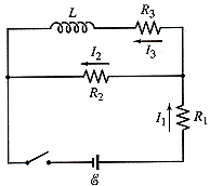
In the figure, ε = 119 V, R1 = 10.7 Ω, R2 = 23.8 Ω, R3...
 In the figure, ε = 119 V, R1 = 10.7 Ω,
R2 = 23.8 Ω, R3 = 26.2 Ω,
and L = 2.70H. Immediately after switch S is closed, what
are (a) i1 and
(b) i2? (Let currents in the
indicated directions have positive values and currents in the
opposite directions have negative values.) A long time later, what
are (c) i1 and
(d) i2? The switch is then
reopened. Just then, what are (e)
i1 and (f)
i2? A...
In the figure, ε = 119 V, R1 = 10.7 Ω,
R2 = 23.8 Ω, R3 = 26.2 Ω,
and L = 2.70H. Immediately after switch S is closed, what
are (a) i1 and
(b) i2? (Let currents in the
indicated directions have positive values and currents in the
opposite directions have negative values.) A long time later, what
are (c) i1 and
(d) i2? The switch is then
reopened. Just then, what are (e)
i1 and (f)
i2? A...
In the figure, ? = 135 V, R1 = 12.1 ?, R2 = 15.1 ?, R3...
 In the figure, ? = 135 V, R1 = 12.1 ?,
R2 = 15.1 ?, R3 = 43.2 ?,
and L = 2.73 H. Immediately after switch S is closed, what
are (a) i1 and
(b) i2? (Let currents in the
indicated directions have positive values and currents in the
opposite directions have negative values.) A long time later, what
are (c) i1 and
(d) i2? The switch is then
reopened. Just then, what are (e)
i1 and (f)
i2?...
In the figure, ? = 135 V, R1 = 12.1 ?,
R2 = 15.1 ?, R3 = 43.2 ?,
and L = 2.73 H. Immediately after switch S is closed, what
are (a) i1 and
(b) i2? (Let currents in the
indicated directions have positive values and currents in the
opposite directions have negative values.) A long time later, what
are (c) i1 and
(d) i2? The switch is then
reopened. Just then, what are (e)
i1 and (f)
i2?...
In the circuit shown in the figure. R1 = 15,00 Ohm, R2 = 10.0 Ohm, R3...
 In the circuit shown in the figure. R1 = 15,00 Ohm, R2 = 10.0 Ohm, R3 = 5.0 Ohm, V emf,1 = 15.0 V. and Vemf,2 = 10.0 V. Using Kirchhoff's Loop and Junction Rules, determine the currents i1, i2, and i3 flowing through R1, R2, and R3, respectively, in the direction indicated in the figure.
Problem 6. The circuit shown below initially has no charge on the capacitors and the switch...
 Problem 6. The circuit shown below initially has no charge on
the capacitors and the switch S is originally open.R1= 4Ω,R2=
6Ω,R3= 8Ω,R4= 8Ω,C1= 2μF, and C2= 6μF.
a) Just after closing the switch S, find the currents I1,I2,I3,
and I4.
b) After the switch has been closed a very long time, find the
currents I1,I2,I3, and I4.
c) After the switch S has been closed for a very long time, find
the potential at points A,B, C, and D....
Problem 6. The circuit shown below initially has no charge on
the capacitors and the switch S is originally open.R1= 4Ω,R2=
6Ω,R3= 8Ω,R4= 8Ω,C1= 2μF, and C2= 6μF.
a) Just after closing the switch S, find the currents I1,I2,I3,
and I4.
b) After the switch has been closed a very long time, find the
currents I1,I2,I3, and I4.
c) After the switch S has been closed for a very long time, find
the potential at points A,B, C, and D....
A circuit is constructed with four resistors, one capacitor, one battery and a switch as shown....
 A circuit is constructed with four resistors, one capacitor, one
battery and a switch as shown. The values for the resistors are: R1
= R2 = 60 Ω, R3 = 49 Ω and R4 = 133 Ω. The capacitance is C = 75 μF
and the battery voltage is V = 24 V.
1)
The switch has been open for a long time when at time t = 0, the
switch is closed. What is I1(0), the magnitude of the...
A circuit is constructed with four resistors, one capacitor, one
battery and a switch as shown. The values for the resistors are: R1
= R2 = 60 Ω, R3 = 49 Ω and R4 = 133 Ω. The capacitance is C = 75 μF
and the battery voltage is V = 24 V.
1)
The switch has been open for a long time when at time t = 0, the
switch is closed. What is I1(0), the magnitude of the...
A circuit is constructed with four resistors, one inductor, one battery and a switch as shown. The values for the resistors are: R1 = R2 = 48 Ω, R3 = 100 Ω and R4 = 130 Ω.
 A circuit is constructed with four resistors, one inductor, one battery and a switch as shown. The values for the resistors are: R1 = R2 = 48 Ω, R3 = 100 Ω and R4 = 130 Ω. The inductance is L = 330 mH and the battery voltage is V = 12 V. The positive terminal of the battery is indicated with a + sign.1)The switch has been open for a long time when at time t = 0, the...
The emfs in the figure below are 1 = 5.00 V and 2 = 18.0 V. The...
 The emfs in the figure below are 1 = 5.00 V
and 2 = 18.0 V. The resistances are
R1 = 18.0 Ω,
R2 = 32.0 Ω,
R3 = 45.5 Ω, and
R4 = 56.0 Ω.
Find the magnitude of the current in each resistor when the
switch is in the following states.
(a) open
I1 =
A
I2 =
A
I3 =
A
I4 =
A
(b) closed
I1 =
A
I2 =
A
I3 =
A
I4 =
A...
The emfs in the figure below are 1 = 5.00 V
and 2 = 18.0 V. The resistances are
R1 = 18.0 Ω,
R2 = 32.0 Ω,
R3 = 45.5 Ω, and
R4 = 56.0 Ω.
Find the magnitude of the current in each resistor when the
switch is in the following states.
(a) open
I1 =
A
I2 =
A
I3 =
A
I4 =
A
(b) closed
I1 =
A
I2 =
A
I3 =
A
I4 =
A...
A circuit is constructed with four resistors, one capacitor, one battery and a switch as shown....
 A circuit is constructed with four resistors, one capacitor, one
battery and a switch as shown. The values for the resistors are:
R1
= R2
= 67 ?, R3
= 96 ? and R4
= 77 ?. The capacitance is C = 48 ?F and the battery voltage is V =
24 V.
Consider the circuit above, with R5
= 67 ? in series with the capacitor. Once again, the switch has
been open for a long time when at...
A circuit is constructed with four resistors, one capacitor, one
battery and a switch as shown. The values for the resistors are:
R1
= R2
= 67 ?, R3
= 96 ? and R4
= 77 ?. The capacitance is C = 48 ?F and the battery voltage is V =
24 V.
Consider the circuit above, with R5
= 67 ? in series with the capacitor. Once again, the switch has
been open for a long time when at...
Consider the following figure. (Assume V = 11 V, R1 = 1.9 Ω, and R2 =...
 Consider the following figure. (Assume V = 11 V,
R1 = 1.9 Ω, and R2 = 1.2
Ω.)
(a) Can the circuit shown above be reduced to a single resistor
connected to the batteries? Explain.
(b) Calculate each of the unknown currents I1,
I2, and I3 for the circuit.
(Give the magnitude of the current only.)
I1 =
A
I2 =
A
I3 =
A
Consider the following figure. (Assume V = 11 V,
R1 = 1.9 Ω, and R2 = 1.2
Ω.)
(a) Can the circuit shown above be reduced to a single resistor
connected to the batteries? Explain.
(b) Calculate each of the unknown currents I1,
I2, and I3 for the circuit.
(Give the magnitude of the current only.)
I1 =
A
I2 =
A
I3 =
A
 In the circuit of the figure = 1.90 kV, C = 8.40 μF, R1 = R2 =
R3 = 0.770 MΩ. With C completely uncharged, switch S is suddenly
closed (at t = 0). At t = 0, what are (a) current i1 in resistor 1,
(b) current i2 in resistor 2, and (c) current i3 in resistor 3? At
t = ∞ (that is, after many time constants), what are (d)i1, (e)i2,
and (f)i3? What is the potential difference...
In the circuit of the figure = 1.90 kV, C = 8.40 μF, R1 = R2 =
R3 = 0.770 MΩ. With C completely uncharged, switch S is suddenly
closed (at t = 0). At t = 0, what are (a) current i1 in resistor 1,
(b) current i2 in resistor 2, and (c) current i3 in resistor 3? At
t = ∞ (that is, after many time constants), what are (d)i1, (e)i2,
and (f)i3? What is the potential difference...
 In the figure, ε = 119 V, R1 = 10.7 Ω,
R2 = 23.8 Ω, R3 = 26.2 Ω,
and L = 2.70H. Immediately after switch S is closed, what
are (a) i1 and
(b) i2? (Let currents in the
indicated directions have positive values and currents in the
opposite directions have negative values.) A long time later, what
are (c) i1 and
(d) i2? The switch is then
reopened. Just then, what are (e)
i1 and (f)
i2? A...
In the figure, ε = 119 V, R1 = 10.7 Ω,
R2 = 23.8 Ω, R3 = 26.2 Ω,
and L = 2.70H. Immediately after switch S is closed, what
are (a) i1 and
(b) i2? (Let currents in the
indicated directions have positive values and currents in the
opposite directions have negative values.) A long time later, what
are (c) i1 and
(d) i2? The switch is then
reopened. Just then, what are (e)
i1 and (f)
i2? A...
 In the figure, ? = 135 V, R1 = 12.1 ?,
R2 = 15.1 ?, R3 = 43.2 ?,
and L = 2.73 H. Immediately after switch S is closed, what
are (a) i1 and
(b) i2? (Let currents in the
indicated directions have positive values and currents in the
opposite directions have negative values.) A long time later, what
are (c) i1 and
(d) i2? The switch is then
reopened. Just then, what are (e)
i1 and (f)
i2?...
In the figure, ? = 135 V, R1 = 12.1 ?,
R2 = 15.1 ?, R3 = 43.2 ?,
and L = 2.73 H. Immediately after switch S is closed, what
are (a) i1 and
(b) i2? (Let currents in the
indicated directions have positive values and currents in the
opposite directions have negative values.) A long time later, what
are (c) i1 and
(d) i2? The switch is then
reopened. Just then, what are (e)
i1 and (f)
i2?...
 In the circuit shown in the figure. R1 = 15,00 Ohm, R2 = 10.0 Ohm, R3 = 5.0 Ohm, V emf,1 = 15.0 V. and Vemf,2 = 10.0 V. Using Kirchhoff's Loop and Junction Rules, determine the currents i1, i2, and i3 flowing through R1, R2, and R3, respectively, in the direction indicated in the figure.
 Problem 6. The circuit shown below initially has no charge on
the capacitors and the switch S is originally open.R1= 4Ω,R2=
6Ω,R3= 8Ω,R4= 8Ω,C1= 2μF, and C2= 6μF.
a) Just after closing the switch S, find the currents I1,I2,I3,
and I4.
b) After the switch has been closed a very long time, find the
currents I1,I2,I3, and I4.
c) After the switch S has been closed for a very long time, find
the potential at points A,B, C, and D....
Problem 6. The circuit shown below initially has no charge on
the capacitors and the switch S is originally open.R1= 4Ω,R2=
6Ω,R3= 8Ω,R4= 8Ω,C1= 2μF, and C2= 6μF.
a) Just after closing the switch S, find the currents I1,I2,I3,
and I4.
b) After the switch has been closed a very long time, find the
currents I1,I2,I3, and I4.
c) After the switch S has been closed for a very long time, find
the potential at points A,B, C, and D....
 A circuit is constructed with four resistors, one capacitor, one
battery and a switch as shown. The values for the resistors are: R1
= R2 = 60 Ω, R3 = 49 Ω and R4 = 133 Ω. The capacitance is C = 75 μF
and the battery voltage is V = 24 V.
1)
The switch has been open for a long time when at time t = 0, the
switch is closed. What is I1(0), the magnitude of the...
A circuit is constructed with four resistors, one capacitor, one
battery and a switch as shown. The values for the resistors are: R1
= R2 = 60 Ω, R3 = 49 Ω and R4 = 133 Ω. The capacitance is C = 75 μF
and the battery voltage is V = 24 V.
1)
The switch has been open for a long time when at time t = 0, the
switch is closed. What is I1(0), the magnitude of the...
 The emfs in the figure below are 1 = 5.00 V
and 2 = 18.0 V. The resistances are
R1 = 18.0 Ω,
R2 = 32.0 Ω,
R3 = 45.5 Ω, and
R4 = 56.0 Ω.
Find the magnitude of the current in each resistor when the
switch is in the following states.
(a) open
I1 =
A
I2 =
A
I3 =
A
I4 =
A
(b) closed
I1 =
A
I2 =
A
I3 =
A
I4 =
A...
The emfs in the figure below are 1 = 5.00 V
and 2 = 18.0 V. The resistances are
R1 = 18.0 Ω,
R2 = 32.0 Ω,
R3 = 45.5 Ω, and
R4 = 56.0 Ω.
Find the magnitude of the current in each resistor when the
switch is in the following states.
(a) open
I1 =
A
I2 =
A
I3 =
A
I4 =
A
(b) closed
I1 =
A
I2 =
A
I3 =
A
I4 =
A...
 A circuit is constructed with four resistors, one capacitor, one
battery and a switch as shown. The values for the resistors are:
R1
= R2
= 67 ?, R3
= 96 ? and R4
= 77 ?. The capacitance is C = 48 ?F and the battery voltage is V =
24 V.
Consider the circuit above, with R5
= 67 ? in series with the capacitor. Once again, the switch has
been open for a long time when at...
A circuit is constructed with four resistors, one capacitor, one
battery and a switch as shown. The values for the resistors are:
R1
= R2
= 67 ?, R3
= 96 ? and R4
= 77 ?. The capacitance is C = 48 ?F and the battery voltage is V =
24 V.
Consider the circuit above, with R5
= 67 ? in series with the capacitor. Once again, the switch has
been open for a long time when at...
 Consider the following figure. (Assume V = 11 V,
R1 = 1.9 Ω, and R2 = 1.2
Ω.)
(a) Can the circuit shown above be reduced to a single resistor
connected to the batteries? Explain.
(b) Calculate each of the unknown currents I1,
I2, and I3 for the circuit.
(Give the magnitude of the current only.)
I1 =
A
I2 =
A
I3 =
A
Consider the following figure. (Assume V = 11 V,
R1 = 1.9 Ω, and R2 = 1.2
Ω.)
(a) Can the circuit shown above be reduced to a single resistor
connected to the batteries? Explain.
(b) Calculate each of the unknown currents I1,
I2, and I3 for the circuit.
(Give the magnitude of the current only.)
I1 =
A
I2 =
A
I3 =
A
Most questions answered within 3 hours.
-
Where is the error in this code sequence?
String s1 = "Hello";
String s2 = "ello";...
asked 10 months ago -
Financial data for Joel de Paris, Inc., for last year
follow:
Joel de Paris, Inc.
Balance...
asked 10 months ago -
Consider this reaction:
Al2(SO4)3 (aq)+ BaCl3
(aq) Al2Cl6 (aq)- +
3BaSO4(s) . What is the...
asked 10 months ago -
Suppose that Savneet is considering increasing her
recent random sample from 20 car rentals to 40...
asked 10 months ago -
Trucks arrive at an unloading terminal at an average rate of 120
per hour.
Trucks arrive...
asked 10 months ago -
Why are methanol and ethanol completely soluble in water while
octanol is not very little soluble....
asked 10 months ago -
A facilities manager at a university reads in a research report
that the mean amount of...
asked 10 months ago -
When the CuSO4 is rehydrated by adding water to the anhydrous
compound, is this an endothermic...
asked 10 months ago -
A ray of sunlight is passing from diamond into crown glass; the
angle of incidence is...
asked 10 months ago -
A block of mass 0.249 kg is placed on top of a light, vertical
spring of...
asked 10 months ago -
how do the kidneys compensate in the presences of acidosis
a) trigger hyperventilate
b) reserve acid...
asked 10 months ago -
Question 501 pts
The rental rate of capital to the firm increases. Which of the
following...
asked 10 months ago