For the circuit shown in the figure find the current through each resistor. For the circuit...

For the circuit shown in the figure find the current through each resistor.
For the circuit shown in the figure find the potential difference across each resistor.
Homework Answers
The concept required to solve the problem are equivalent resistance and ohm’s law.
The circuit diagram is given. Therefore, equivalent resistance of the circuit can be derived using combination of resistors. Further, as the voltage of the source is known, current through the circuit can be derived. Further, potential drop can across each resistor can be calculated using Ohm’s Law.
Resistor is an electronic device that restricts passing of current through it. Resistors of different values can be connected in any combination in a circuit.
The equivalent resistance of the circuit is the total resistance to current in the circuit. The equivalent resistance for different combination can be divided into series combination of resistors and parallel combination of resistors.
Series combination:
In series combination, resistors are connected on the same branch. The current passing through series resistors is same.
Equivalent resistance for series combination is given by

Parallel combination:
In parallel combination, resistors are connected on different branch such that potential drop across them is same.
Equivalent resistance for parallel combination is given by

Ohm’s law states that, “The electric current through a circuit is directly proportional to the voltage applied and the inversely proportional to the resistance of the circuit.”
(a)
As resistor are parallel,

As  are connected in series

As  are parallel

As  and 2
and 2 are connected in series

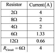
Now, current through circuit

Substitute 24 V for  and
and  for
for 

As 
Current through both of them is same and equal to current through circuit

In  , 8
, 8 and
and  are connected parallel and have same resistance, current in them will be equally divided.
Therefore,

In  ,
,  are in series, therefore, current though them is same and equal to 2A

In  ,
,  are connected parallel,
  will be divided amongst them according to their resistance. Since
  is half the value of 12
 , the current passing through it will be double.
Therefore,

(b)
The voltage drops across each resistor can be given by

Across  resistor

Across  resistor

Across  resistor

Across  resistor

As Across  resistor

The current through each resistor is given by
The voltage-drop across each resistor is given by

Add Answer to:
For the circuit shown in the figure find the current through
each resistor.
For the circuit...
A. For the circuit shown in the figure(Figure 1) find the current through each resistor. B....
 A. For the circuit shown in the figure(Figure 1) find the
current through each resistor.
B. For the circuit shown in the figure find the potential
difference across each resistor.
24 V 4 Ω
A. For the circuit shown in the figure(Figure 1) find the
current through each resistor.
B. For the circuit shown in the figure find the potential
difference across each resistor.
24 V 4 Ω
For the circuit shown in the figure, find the current through and the potential difference across each resistor.
 For the circuit shown in the figure, find the current through
and the potential difference across each resistor.What is the current through the 3 Ω resistor?What is the current through the 4 Ω resistor? What is the potential difference across the 3 Ω resistor.What is the potential difference across the 4 Ω resistor?What is the potential difference across the 48 Ω resistor?What is the current through the 48 Ω resistor?What is the potential difference
across the 16 Ω resistor?What is the...
For the circuit shown in the figure, find the current through
and the potential difference across each resistor.What is the current through the 3 Ω resistor?What is the current through the 4 Ω resistor? What is the potential difference across the 3 Ω resistor.What is the potential difference across the 4 Ω resistor?What is the potential difference across the 48 Ω resistor?What is the current through the 48 Ω resistor?What is the potential difference
across the 16 Ω resistor?What is the...
For each circuit shown in the figure, find the current through and potential difference across each...
 For each circuit shown in the figure, find the current through
and potential difference across each resistor
Thank you!
4Ω 6Ω 24 V 24 Ω 812 24 Ω
For each circuit shown in the figure, find the current through
and potential difference across each resistor
Thank you!
4Ω 6Ω 24 V 24 Ω 812 24 Ω
a) For the circuit shown in the figure find the currentthrough each resistor.b) For...
 a) For the circuit shown in the figure find the current
through each resistor.b) For the circuit shown in the figure find the potential
difference across each resistor.
a) For the circuit shown in the figure find the current
through each resistor.b) For the circuit shown in the figure find the potential
difference across each resistor.
For the circuit shown in the figure (Figure 1), find the current through and the potential...
 For the circuit shown in the figure (Figure 1), find the current through and the potential difference across each resistor. For the steps and strategies involved in solving a similar problem, you may view a Video Tutor Solution.
1 Circuit Analysis For the circuit shown in Figure 1, find the current through and the...
 1 Circuit Analysis For the circuit shown in Figure 1, find the current through and the potential difference across each resistor. Place your results in a table for ease of reading. Please follow the context-Rich solution format. For sense-making, please try to reason why the amount of current through each resistor makes sense. Figure 1: 3 Ω 16 Ω 4822 12 V 412
(A) For the circuit shown in the figure(Figure 1) find thecurrent through each resistor.Express...
 (A) For the circuit shown in the figure(Figure 1) find the
current through each resistor.Express your answers using two significant figures. Enter your
answers numerically separated by commas.(B)For the circuit shown in the figure find the potential
difference across each resistor.Express your answers using two significant figures. Enter your
answers numerically separated by commas.
(A) For the circuit shown in the figure(Figure 1) find the
current through each resistor.Express your answers using two significant figures. Enter your
answers numerically separated by commas.(B)For the circuit shown in the figure find the potential
difference across each resistor.Express your answers using two significant figures. Enter your
answers numerically separated by commas.
For the circuit shown in the figure below, find the current through and the potential difference...
 For the circuit shown in the figure below, find the current through and the potential difference across each resistor. Place your results in the table for ease of reading. (Assume R1 = 27 ohm, R2 = 2 ohm, and V = 2 V.)
Chapter 27, Problem 21. Find the current through each resistor in the circuit shown in Figure...
 Chapter 27, Problem 21. Find the current through each resistor in the circuit shown in Figure 27.P10 Find the potential difference between points A and H. Which point is at the higher potential? Use these values: epsilon_i - 12.0 V, epsilon_2 = 8.00 V. R_1 = 4.00 k Ohm, R_2 = 4.00 k Ohm, R_3 = 2.00 k Ohm
Find current and potential difference across each resistor
 a.) Find the current through resistor a) in the figure.b.) Find the potential difference across resistor a) in the figure.c.) Find the current through resistor b) in the figure.d.) Find the potential difference across resistor b) in the figure.e.) Find the current through resistor c) in the figure.f.) Find the potential difference across resistor c) in the figure.g.) Find the current through resistor d) in the figure.h.) Find the potential difference across resistor d) in the figure.I can tell that...
 A. For the circuit shown in the figure(Figure 1) find the
current through each resistor.
B. For the circuit shown in the figure find the potential
difference across each resistor.
24 V 4 Ω
A. For the circuit shown in the figure(Figure 1) find the
current through each resistor.
B. For the circuit shown in the figure find the potential
difference across each resistor.
24 V 4 Ω
 For the circuit shown in the figure, find the current through
and the potential difference across each resistor.What is the current through the 3 Ω resistor?What is the current through the 4 Ω resistor? What is the potential difference across the 3 Ω resistor.What is the potential difference across the 4 Ω resistor?What is the potential difference across the 48 Ω resistor?What is the current through the 48 Ω resistor?What is the potential difference
across the 16 Ω resistor?What is the...
For the circuit shown in the figure, find the current through
and the potential difference across each resistor.What is the current through the 3 Ω resistor?What is the current through the 4 Ω resistor? What is the potential difference across the 3 Ω resistor.What is the potential difference across the 4 Ω resistor?What is the potential difference across the 48 Ω resistor?What is the current through the 48 Ω resistor?What is the potential difference
across the 16 Ω resistor?What is the...
 For each circuit shown in the figure, find the current through
and potential difference across each resistor
Thank you!
4Ω 6Ω 24 V 24 Ω 812 24 Ω
For each circuit shown in the figure, find the current through
and potential difference across each resistor
Thank you!
4Ω 6Ω 24 V 24 Ω 812 24 Ω
 a) For the circuit shown in the figure find the current
through each resistor.b) For the circuit shown in the figure find the potential
difference across each resistor.
a) For the circuit shown in the figure find the current
through each resistor.b) For the circuit shown in the figure find the potential
difference across each resistor.
 For the circuit shown in the figure (Figure 1), find the current through and the potential difference across each resistor. For the steps and strategies involved in solving a similar problem, you may view a Video Tutor Solution.
 1 Circuit Analysis For the circuit shown in Figure 1, find the current through and the potential difference across each resistor. Place your results in a table for ease of reading. Please follow the context-Rich solution format. For sense-making, please try to reason why the amount of current through each resistor makes sense. Figure 1: 3 Ω 16 Ω 4822 12 V 412
 (A) For the circuit shown in the figure(Figure 1) find the
current through each resistor.Express your answers using two significant figures. Enter your
answers numerically separated by commas.(B)For the circuit shown in the figure find the potential
difference across each resistor.Express your answers using two significant figures. Enter your
answers numerically separated by commas.
(A) For the circuit shown in the figure(Figure 1) find the
current through each resistor.Express your answers using two significant figures. Enter your
answers numerically separated by commas.(B)For the circuit shown in the figure find the potential
difference across each resistor.Express your answers using two significant figures. Enter your
answers numerically separated by commas.
 For the circuit shown in the figure below, find the current through and the potential difference across each resistor. Place your results in the table for ease of reading. (Assume R1 = 27 ohm, R2 = 2 ohm, and V = 2 V.)
 Chapter 27, Problem 21. Find the current through each resistor in the circuit shown in Figure 27.P10 Find the potential difference between points A and H. Which point is at the higher potential? Use these values: epsilon_i - 12.0 V, epsilon_2 = 8.00 V. R_1 = 4.00 k Ohm, R_2 = 4.00 k Ohm, R_3 = 2.00 k Ohm
Most questions answered within 3 hours.
-
Where is the error in this code sequence?
String s1 = "Hello";
String s2 = "ello";...
asked 10 months ago -
Financial data for Joel de Paris, Inc., for last year
follow:
Joel de Paris, Inc.
Balance...
asked 10 months ago -
Consider this reaction:
Al2(SO4)3 (aq)+ BaCl3
(aq) Al2Cl6 (aq)- +
3BaSO4(s) . What is the...
asked 10 months ago -
Suppose that Savneet is considering increasing her
recent random sample from 20 car rentals to 40...
asked 10 months ago -
Trucks arrive at an unloading terminal at an average rate of 120
per hour.
Trucks arrive...
asked 10 months ago -
Why are methanol and ethanol completely soluble in water while
octanol is not very little soluble....
asked 10 months ago -
A facilities manager at a university reads in a research report
that the mean amount of...
asked 10 months ago -
When the CuSO4 is rehydrated by adding water to the anhydrous
compound, is this an endothermic...
asked 10 months ago -
A ray of sunlight is passing from diamond into crown glass; the
angle of incidence is...
asked 10 months ago -
A block of mass 0.249 kg is placed on top of a light, vertical
spring of...
asked 10 months ago -
how do the kidneys compensate in the presences of acidosis
a) trigger hyperventilate
b) reserve acid...
asked 10 months ago -
Question 501 pts
The rental rate of capital to the firm increases. Which of the
following...
asked 10 months ago