
Homework Answers


![236 ar Co.840 (690) ) 1437 mPa. b= -f log [festat ] - - f long (0.94 inche] b = -0.1308 0.844 x 690 236 Then , nev Number of](http://img.homeworklib.com/questions/c13a4c70-1f1e-11eb-ad17-797502b98422.png?x-oss-process=image/resize,w_560)
Add Answer to:
answer with steps please
4. Figure below shows a rotating shaft simply supported in ball bearings...
Please answer A and B. The rotating solid stedl shaft is simply supported by bearings at...
 Please answer A and B.
The rotating solid stedl shaft is simply supported by bearings at points B and C and is driven by a gear (not shown) which meshes with the spur gear at D, which has a 150-mm pitch diameter. The force F from the drive gear acts at a pressure angle of 20. The shaft transmits a torque to point A of TA-340 N m. The shaft is machined from steel with Sy- 420 MPa and Sut-560...
Please answer A and B.
The rotating solid stedl shaft is simply supported by bearings at points B and C and is driven by a gear (not shown) which meshes with the spur gear at D, which has a 150-mm pitch diameter. The force F from the drive gear acts at a pressure angle of 20. The shaft transmits a torque to point A of TA-340 N m. The shaft is machined from steel with Sy- 420 MPa and Sut-560...
The rotating solid steel shaft is simply supported by bearings at points B and C and...
 The rotating solid steel shaft is simply supported by bearings at points B and C and is driven by a gear (not shown) which meshes with the spur gear at D, which has a 150-mm pitch diameter. The force F from the drive gear acts at a pressure angle of 20°. The shaft transmits a torque to point A of T 400 N m. The shaft is machined from steel with S, 420 MPa and Su 560 MPa. Using a...
The rotating shaft shown below is supported by self aligning bearings at A and D. The diameter of...
 The rotating shaft shown below is supported by self aligning bearings at A and D. The diameter of the shaft changes from D-1.5" to d-1.0" at the midpoint of the shaft. The radius of the fillet at the diameter change is r-0.2" and all surfaces are machined. The shaft is made of normalized 1020 steel having . 64.0 ksi and S, = 50.3 ksi . The shaft is loaded with 250-lb forces at B and C as shown to create...
augue application? 6-10 A rotating shaft of 25-mm diameter is simply supported by bearing reaction forces R and R2. The...
 augue application? 6-10 A rotating shaft of 25-mm diameter is simply supported by bearing reaction forces R and R2. The shaft is loaded with a transverse load of 13 kN as shown in the figure. The shaft is made from AISI 1045 hot-rolled steel. The surface has been machined. Determine (a) the minimum static factor of safety based on yielding. (b) the endurance limit, adjusted as necessary with Marin factors. (c) the minimum fatigue factor of safety based on achieving...
A rotating shaft of 25-mm diameter is simply supported by bearing reaction forces R and R. The shaft is loaded with a transverse load of 13 kN as shown in the figure.
 A rotating shaft of 25-mm diameter is simply supported by bearing reaction forces R and R. The shaft is loaded with a transverse load of 13 kN as shown in the figure. The shaft is made from AISI 1045 hot-rolled steel. The surface has been machined. Determine (a) the minimum static factor of safety based on yielding. (b) the endurance limit, adjusted as necessary with Marin factors. (c) the minimum fatigue factor of safety based on achieving infinite life. (d) If the fatigue factor...
The rotating solid steel shaft is simply supported by bearings at points B and C and is driven by gear (not shown) which meshes with the spur gear at D
 The rotating solid steel shaft is simply supported by bearings at points B and C and is driven by gear (not shown) which meshes with the spur gear at D, which has a 150-mm pitch diameter. The force F from the drive gear acts at a pressure angle of 20". The shaft transmits a torque to point A of TA = 340 N.m. The shaft is machined from steel with Sy= 420 MPa and Sut = 560 MPa. The fatigue...
pls solve with all the steps and correct solutions only! will rate! thanks The shaft shown...
 pls
solve with all the steps and correct solutions only! will rate!
thanks
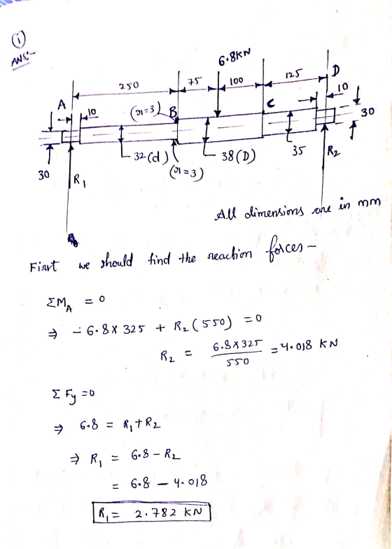
The shaft shown in the figure is supported on bearings located at A and D. The shaft is made from AISI 1050 steel with a yield strength of 580 MPa and an ultimate strength of 690 MPa. The shaft dimensions are in millimeters and each step has the diameter shown. There are fillets with 2 mm radii at each step in the diameter. The shaft has a...
pls
solve with all the steps and correct solutions only! will rate!
thanks
The shaft shown in the figure is supported on bearings located at A and D. The shaft is made from AISI 1050 steel with a yield strength of 580 MPa and an ultimate strength of 690 MPa. The shaft dimensions are in millimeters and each step has the diameter shown. There are fillets with 2 mm radii at each step in the diameter. The shaft has a...
The shaft shown in Figure is supported by bearings cach end, which have bores of 20.0...
 The shaft shown in Figure is supported by bearings cach end, which have bores of 20.0 mm. Design the shaft to carry the given load if it is steady and the shaft is stationary. Make the dimension a as large as possible while keeping the stress safe. Determine the required diameter in the middle portion. The maximum fillet permissible is 2.0 mm. Use SAE 1137 cold-drawn steel. Use a design factor of 3 The material properties are as follows:- Q-1...
A simply supported shaft shown below is subjected to a constant load P and a time varying torque,...
 A simply supported shaft shown below is subjected to a constant load P and a time varying torque, Tmin to Tmax Find the shaft diameter for a factor of safety of 2 for fatigue with the following information for the steel shaft. Se = 180 MPa, Sy = 450 MPa, Sut = 600 MPa P- 5 kN, Tmin 0, Tmax-150 N-m a-400 mm, b 550 mm, I 575 mm
A simply supported shaft shown below is subjected to a constant...
A simply supported shaft shown below is subjected to a constant load P and a time varying torque, Tmin to Tmax Find the shaft diameter for a factor of safety of 2 for fatigue with the following information for the steel shaft. Se = 180 MPa, Sy = 450 MPa, Sut = 600 MPa P- 5 kN, Tmin 0, Tmax-150 N-m a-400 mm, b 550 mm, I 575 mm
A simply supported shaft shown below is subjected to a constant...
The shaft shown in the figure is supported on bearings located at A and D. The...
 The shaft shown in the figure is supported on bearings located at A and D. The shaft is made from steel with a yield strength of 680 MPa and an ultimate strength of 790 MPa. The shaft dimensions are in millimeters and each step has the diameter shown. There are fillets with 2 mm radii at each step in the diameter. The notch sensitivity is 0.840. The shaft has a machined surface finish. A reliability of 99% is desired for...
 Please answer A and B.
The rotating solid stedl shaft is simply supported by bearings at points B and C and is driven by a gear (not shown) which meshes with the spur gear at D, which has a 150-mm pitch diameter. The force F from the drive gear acts at a pressure angle of 20. The shaft transmits a torque to point A of TA-340 N m. The shaft is machined from steel with Sy- 420 MPa and Sut-560...
Please answer A and B.
The rotating solid stedl shaft is simply supported by bearings at points B and C and is driven by a gear (not shown) which meshes with the spur gear at D, which has a 150-mm pitch diameter. The force F from the drive gear acts at a pressure angle of 20. The shaft transmits a torque to point A of TA-340 N m. The shaft is machined from steel with Sy- 420 MPa and Sut-560...
 The rotating solid steel shaft is simply supported by bearings at points B and C and is driven by a gear (not shown) which meshes with the spur gear at D, which has a 150-mm pitch diameter. The force F from the drive gear acts at a pressure angle of 20°. The shaft transmits a torque to point A of T 400 N m. The shaft is machined from steel with S, 420 MPa and Su 560 MPa. Using a...
 The rotating shaft shown below is supported by self aligning bearings at A and D. The diameter of the shaft changes from D-1.5" to d-1.0" at the midpoint of the shaft. The radius of the fillet at the diameter change is r-0.2" and all surfaces are machined. The shaft is made of normalized 1020 steel having . 64.0 ksi and S, = 50.3 ksi . The shaft is loaded with 250-lb forces at B and C as shown to create...
 augue application? 6-10 A rotating shaft of 25-mm diameter is simply supported by bearing reaction forces R and R2. The shaft is loaded with a transverse load of 13 kN as shown in the figure. The shaft is made from AISI 1045 hot-rolled steel. The surface has been machined. Determine (a) the minimum static factor of safety based on yielding. (b) the endurance limit, adjusted as necessary with Marin factors. (c) the minimum fatigue factor of safety based on achieving...
 pls
solve with all the steps and correct solutions only! will rate!
thanks
The shaft shown in the figure is supported on bearings located at A and D. The shaft is made from AISI 1050 steel with a yield strength of 580 MPa and an ultimate strength of 690 MPa. The shaft dimensions are in millimeters and each step has the diameter shown. There are fillets with 2 mm radii at each step in the diameter. The shaft has a...
pls
solve with all the steps and correct solutions only! will rate!
thanks
The shaft shown in the figure is supported on bearings located at A and D. The shaft is made from AISI 1050 steel with a yield strength of 580 MPa and an ultimate strength of 690 MPa. The shaft dimensions are in millimeters and each step has the diameter shown. There are fillets with 2 mm radii at each step in the diameter. The shaft has a...
 The shaft shown in Figure is supported by bearings cach end, which have bores of 20.0 mm. Design the shaft to carry the given load if it is steady and the shaft is stationary. Make the dimension a as large as possible while keeping the stress safe. Determine the required diameter in the middle portion. The maximum fillet permissible is 2.0 mm. Use SAE 1137 cold-drawn steel. Use a design factor of 3 The material properties are as follows:- Q-1...
 A simply supported shaft shown below is subjected to a constant load P and a time varying torque, Tmin to Tmax Find the shaft diameter for a factor of safety of 2 for fatigue with the following information for the steel shaft. Se = 180 MPa, Sy = 450 MPa, Sut = 600 MPa P- 5 kN, Tmin 0, Tmax-150 N-m a-400 mm, b 550 mm, I 575 mm
A simply supported shaft shown below is subjected to a constant...
A simply supported shaft shown below is subjected to a constant load P and a time varying torque, Tmin to Tmax Find the shaft diameter for a factor of safety of 2 for fatigue with the following information for the steel shaft. Se = 180 MPa, Sy = 450 MPa, Sut = 600 MPa P- 5 kN, Tmin 0, Tmax-150 N-m a-400 mm, b 550 mm, I 575 mm
A simply supported shaft shown below is subjected to a constant...
 The shaft shown in the figure is supported on bearings located at A and D. The shaft is made from steel with a yield strength of 680 MPa and an ultimate strength of 790 MPa. The shaft dimensions are in millimeters and each step has the diameter shown. There are fillets with 2 mm radii at each step in the diameter. The notch sensitivity is 0.840. The shaft has a machined surface finish. A reliability of 99% is desired for...
Most questions answered within 3 hours.
-
Where is the error in this code sequence?
String s1 = "Hello";
String s2 = "ello";...
asked 10 months ago -
Financial data for Joel de Paris, Inc., for last year
follow:
Joel de Paris, Inc.
Balance...
asked 10 months ago -
Consider this reaction:
Al2(SO4)3 (aq)+ BaCl3
(aq) Al2Cl6 (aq)- +
3BaSO4(s) . What is the...
asked 10 months ago -
Suppose that Savneet is considering increasing her
recent random sample from 20 car rentals to 40...
asked 10 months ago -
Trucks arrive at an unloading terminal at an average rate of 120
per hour.
Trucks arrive...
asked 10 months ago -
Why are methanol and ethanol completely soluble in water while
octanol is not very little soluble....
asked 10 months ago -
A facilities manager at a university reads in a research report
that the mean amount of...
asked 10 months ago -
When the CuSO4 is rehydrated by adding water to the anhydrous
compound, is this an endothermic...
asked 10 months ago -
A ray of sunlight is passing from diamond into crown glass; the
angle of incidence is...
asked 10 months ago -
A block of mass 0.249 kg is placed on top of a light, vertical
spring of...
asked 10 months ago -
how do the kidneys compensate in the presences of acidosis
a) trigger hyperventilate
b) reserve acid...
asked 10 months ago -
Question 501 pts
The rental rate of capital to the firm increases. Which of the
following...
asked 10 months ago