

Homework Answers
Here is the solution of your question. If you have any doubt or
need any clarification please comment in comment box and will
definitely resolve your query. If you find useful please upvote it.
Thanks in advance.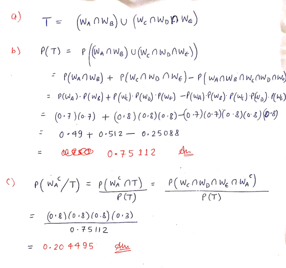
Add Answer to:
5. The figure below shows an electrical circuit in which each of the components located at...
Find the power of the signal conponent of a P is the Fourice t of s,(0)(2.5 points) edf,where S.f density of pu nose (2.5 points) . Consider the RL circuit shown below. Assume that R-10 and L-IN....
 Find the power of the signal conponent of a P is the Fourice t of s,(0)(2.5 points) edf,where S.f density of pu nose (2.5 points) . Consider the RL circuit shown below. Assume that R-10 and L-IN. Hint : Use Parseval's relationship if necessary i(t) e. What is the input signal-o-oise (SNR,ratio, defined as: SNR, 1olog..C)as polnts d. Find the output power spectral density of noise N,00 N,( HP, where HU) is the frequency response of the circuit, and N,(n)...
Suppose a system of ive components Ai,1 Si S 5 is arranged as follows 2 Assum e the lifetime of each component is exponentially distributed with parameter) and the components function independently....
 Suppose a system of ive components Ai,1 Si S 5 is arranged as follows 2 Assum e the lifetime of each component is exponentially distributed with parameter) and the components function independently. Let of the i-th component, that is the random variable defined by (Xi - t) means that the the i-th component stops working at time t. Saying that Xi has an exponenti distribution with parameter X means X, be the lifetime random variable and P(Xi s t)-1-e*. be...
Consider the RC circuit shown below. Assume that R=(0.1)2 and C=(0.1)F 3. R i(t) y (t)...
 Consider the RC circuit shown below. Assume that R=(0.1)2 and C=(0.1)F 3. R i(t) y (t) x(t) The input to this circuit is given as x(t) s(t)+ny (t), where the noise component of input, n(t), is a sample function realization of white noise process with an autocorrelation function given by Rpx(t) 8(T), and s (t) cos(6Tt) is the signal component of input. IS(fOI df, where S( a. Find the power of the signal component of input, Ps is the Fourier...
The options are A-K for each "select" box The diagram below shows the components that you...
 The options are A-K for each
"select" box
The diagram below shows the components that you will use in the circuit diagram for this experiment. DE Signal Interface -I main unit Power Output B A (a) You start with connecting wire 1 from the terminal that is colored black on the main unit of the apparatus. Where on the multimeter will you connect the free end of wire 1? -Select ▲ (b) You now use a second connecting wire, wire...
The options are A-K for each
"select" box
The diagram below shows the components that you will use in the circuit diagram for this experiment. DE Signal Interface -I main unit Power Output B A (a) You start with connecting wire 1 from the terminal that is colored black on the main unit of the apparatus. Where on the multimeter will you connect the free end of wire 1? -Select ▲ (b) You now use a second connecting wire, wire...
Suppose a computer system is assembled out of 100 components, and these are completely assembled before...
 Suppose a computer system is assembled out of 100 components, and these are completely assembled before the power is ever applied. Assume that the computer fails to work properly if any component fails a) the rate of defects or each component of the system is only 0 22%, what is the probability that the assembled computer works when switched on, assuming the components are independent? b) For the probability that the system works to be 99% what is the largest...
2.7. Consider the differential equation for the RC circuit in Fig. P.2.12: Figure P. 2.12 R=1...
 2.7. Consider the differential equation for the RC circuit in Fig. P.2.12: Figure P. 2.12 R=1 r(t) =tu(t) C=1/4F y(t) (b) dy(t)dt+4y(t)=4x(t) Let the input signal be a unit step, that is, x(t) = u(1). Using the first-order differential equation solution technique discussed in Section 2.5.1 find the solution y(t) for t2 0 subject to each initial condition specified below: a. y (O) = 0 b. y (O) = 5 c. y (0) = 1 d. y (0) = -1...
ASAP Exercise 6. This problem describes an experiment in which conditional probabilities are used to compute...
 ASAP
Exercise 6. This problem describes an experiment in which conditional probabilities are used to compute "proper" probability. The experiment starts with two urns, Urn #1 contains 5 white marbles and 2 black marbles. Urn #2 contains 7 white marbles and 3 black marbles. One marble from each urn is drawn at random. (For each urn, the chance of each marble being drawn is the same.) Let T be the event that the two marbles are the same color. Let...
ASAP
Exercise 6. This problem describes an experiment in which conditional probabilities are used to compute "proper" probability. The experiment starts with two urns, Urn #1 contains 5 white marbles and 2 black marbles. Urn #2 contains 7 white marbles and 3 black marbles. One marble from each urn is drawn at random. (For each urn, the chance of each marble being drawn is the same.) Let T be the event that the two marbles are the same color. Let...
1. Given i(t) Cut) Figure 2.1: Step voltage applied to a series RLC circuit. (a) Verify...
 1. Given i(t) Cut) Figure 2.1: Step voltage applied to a series RLC circuit. (a) Verify that the differential equation for v(t) is found as dt2 L dt LC LC (b) If v(0)-5 V and i(0)-OA. find the voltage response, u(t), for t >0 when v, 5V, R#330 n, L-100 mil, C., 0.1uF (c) Now suppose we replace the 5 V source in our circuit with a squarewave as shown below: w(t) Figure 2.2 From the response of v(t) that...
please answer this ASAP Answer the following questions for the below BJT amplifier circuit. Assume capacitors...
 please answer this ASAP
Answer the following questions for the below BJT amplifier circuit. Assume capacitors are short in the signal circuit. Use Vr 25 mV,B = 100, Vpo = 0.7 V, and Ignore the early effect in the bias and signal circuits Find the Bias parameters of the amplifier circuit a) b) Find the small signal parameters of the amplifier. c) Draw the small signal equivalent circuit. Find the open loop voltage gain (Ayo), voltage gain (A,), total circuit...
please answer this ASAP
Answer the following questions for the below BJT amplifier circuit. Assume capacitors are short in the signal circuit. Use Vr 25 mV,B = 100, Vpo = 0.7 V, and Ignore the early effect in the bias and signal circuits Find the Bias parameters of the amplifier circuit a) b) Find the small signal parameters of the amplifier. c) Draw the small signal equivalent circuit. Find the open loop voltage gain (Ayo), voltage gain (A,), total circuit...
 Find the power of the signal conponent of a P is the Fourice t of s,(0)(2.5 points) edf,where S.f density of pu nose (2.5 points) . Consider the RL circuit shown below. Assume that R-10 and L-IN. Hint : Use Parseval's relationship if necessary i(t) e. What is the input signal-o-oise (SNR,ratio, defined as: SNR, 1olog..C)as polnts d. Find the output power spectral density of noise N,00 N,( HP, where HU) is the frequency response of the circuit, and N,(n)...
 Suppose a system of ive components Ai,1 Si S 5 is arranged as follows 2 Assum e the lifetime of each component is exponentially distributed with parameter) and the components function independently. Let of the i-th component, that is the random variable defined by (Xi - t) means that the the i-th component stops working at time t. Saying that Xi has an exponenti distribution with parameter X means X, be the lifetime random variable and P(Xi s t)-1-e*. be...
 Consider the RC circuit shown below. Assume that R=(0.1)2 and C=(0.1)F 3. R i(t) y (t) x(t) The input to this circuit is given as x(t) s(t)+ny (t), where the noise component of input, n(t), is a sample function realization of white noise process with an autocorrelation function given by Rpx(t) 8(T), and s (t) cos(6Tt) is the signal component of input. IS(fOI df, where S( a. Find the power of the signal component of input, Ps is the Fourier...
 Consider the RC circuit shown below. Assume that R=(0.1)2 and C=(0.1)F 3. R i(t) y (t) x(t) The input to this circuit is given as x(t) s(t)+ny (t), where the noise component of input, n(t), is a sample function realization of white noise process with an autocorrelation function given by Rpx(t) 8(T), and s (t) cos(6Tt) is the signal component of input. IS(fOI df, where S( a. Find the power of the signal component of input, Ps is the Fourier...
 The options are A-K for each
"select" box
The diagram below shows the components that you will use in the circuit diagram for this experiment. DE Signal Interface -I main unit Power Output B A (a) You start with connecting wire 1 from the terminal that is colored black on the main unit of the apparatus. Where on the multimeter will you connect the free end of wire 1? -Select ▲ (b) You now use a second connecting wire, wire...
The options are A-K for each
"select" box
The diagram below shows the components that you will use in the circuit diagram for this experiment. DE Signal Interface -I main unit Power Output B A (a) You start with connecting wire 1 from the terminal that is colored black on the main unit of the apparatus. Where on the multimeter will you connect the free end of wire 1? -Select ▲ (b) You now use a second connecting wire, wire...
 Suppose a computer system is assembled out of 100 components, and these are completely assembled before the power is ever applied. Assume that the computer fails to work properly if any component fails a) the rate of defects or each component of the system is only 0 22%, what is the probability that the assembled computer works when switched on, assuming the components are independent? b) For the probability that the system works to be 99% what is the largest...
 2.7. Consider the differential equation for the RC circuit in Fig. P.2.12: Figure P. 2.12 R=1 r(t) =tu(t) C=1/4F y(t) (b) dy(t)dt+4y(t)=4x(t) Let the input signal be a unit step, that is, x(t) = u(1). Using the first-order differential equation solution technique discussed in Section 2.5.1 find the solution y(t) for t2 0 subject to each initial condition specified below: a. y (O) = 0 b. y (O) = 5 c. y (0) = 1 d. y (0) = -1...
 ASAP
Exercise 6. This problem describes an experiment in which conditional probabilities are used to compute "proper" probability. The experiment starts with two urns, Urn #1 contains 5 white marbles and 2 black marbles. Urn #2 contains 7 white marbles and 3 black marbles. One marble from each urn is drawn at random. (For each urn, the chance of each marble being drawn is the same.) Let T be the event that the two marbles are the same color. Let...
ASAP
Exercise 6. This problem describes an experiment in which conditional probabilities are used to compute "proper" probability. The experiment starts with two urns, Urn #1 contains 5 white marbles and 2 black marbles. Urn #2 contains 7 white marbles and 3 black marbles. One marble from each urn is drawn at random. (For each urn, the chance of each marble being drawn is the same.) Let T be the event that the two marbles are the same color. Let...
 1. Given i(t) Cut) Figure 2.1: Step voltage applied to a series RLC circuit. (a) Verify that the differential equation for v(t) is found as dt2 L dt LC LC (b) If v(0)-5 V and i(0)-OA. find the voltage response, u(t), for t >0 when v, 5V, R#330 n, L-100 mil, C., 0.1uF (c) Now suppose we replace the 5 V source in our circuit with a squarewave as shown below: w(t) Figure 2.2 From the response of v(t) that...
 please answer this ASAP
Answer the following questions for the below BJT amplifier circuit. Assume capacitors are short in the signal circuit. Use Vr 25 mV,B = 100, Vpo = 0.7 V, and Ignore the early effect in the bias and signal circuits Find the Bias parameters of the amplifier circuit a) b) Find the small signal parameters of the amplifier. c) Draw the small signal equivalent circuit. Find the open loop voltage gain (Ayo), voltage gain (A,), total circuit...
please answer this ASAP
Answer the following questions for the below BJT amplifier circuit. Assume capacitors are short in the signal circuit. Use Vr 25 mV,B = 100, Vpo = 0.7 V, and Ignore the early effect in the bias and signal circuits Find the Bias parameters of the amplifier circuit a) b) Find the small signal parameters of the amplifier. c) Draw the small signal equivalent circuit. Find the open loop voltage gain (Ayo), voltage gain (A,), total circuit...
Most questions answered within 3 hours.
-
Where is the error in this code sequence?
String s1 = "Hello";
String s2 = "ello";...
asked 10 months ago -
Financial data for Joel de Paris, Inc., for last year
follow:
Joel de Paris, Inc.
Balance...
asked 10 months ago -
Consider this reaction:
Al2(SO4)3 (aq)+ BaCl3
(aq) Al2Cl6 (aq)- +
3BaSO4(s) . What is the...
asked 10 months ago -
Suppose that Savneet is considering increasing her
recent random sample from 20 car rentals to 40...
asked 10 months ago -
Trucks arrive at an unloading terminal at an average rate of 120
per hour.
Trucks arrive...
asked 10 months ago -
Why are methanol and ethanol completely soluble in water while
octanol is not very little soluble....
asked 10 months ago -
A facilities manager at a university reads in a research report
that the mean amount of...
asked 10 months ago -
When the CuSO4 is rehydrated by adding water to the anhydrous
compound, is this an endothermic...
asked 10 months ago -
A ray of sunlight is passing from diamond into crown glass; the
angle of incidence is...
asked 10 months ago -
A block of mass 0.249 kg is placed on top of a light, vertical
spring of...
asked 10 months ago -
how do the kidneys compensate in the presences of acidosis
a) trigger hyperventilate
b) reserve acid...
asked 10 months ago -
Question 501 pts
The rental rate of capital to the firm increases. Which of the
following...
asked 10 months ago