The shaper mechanism is designed to give a slow cutting stroke and a quick return to a blade attached to the slider at C. (Figure 1).
The shaper mechanism is designed to give a slow cutting stroke and a quick return to a blade attached to the slider at C. (Figure 1).
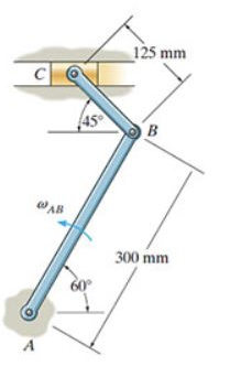
Part A
Determine the angular velocity of the link CB at the instant shown measured clockwise, if the link AB is rotating at 4.6 rad/s.
Homework Answers

look at example 2
Add Answer to:
The shaper mechanism is designed to give a slow cutting stroke and a quick return to a blade attached to the slider at C. (Figure 1).
BONUS QUESTION (6 marks) Ve- 1.2 m/secThe shaper mechanism is designed to give a slow cutting str...
 BONUS QUESTIONThe shaper mechanism is designed to give a slow cutting stroke and a quick return to a blade attached to a slider at C. What angular velocity of AB (in RPM and in radians/sec) is needed if the piston is required to move to the right at 1.2 m/sec at the instant shown?
QUESTION 1 The slider block C moves at 8 m/s down the inclined groove. Determine the...
 QUESTION 1 The slider block C moves at 8 m/s down the inclined groove. Determine the angular velocities of links AB and BC.at the instant shown QUESTION 3 At the instant shown. θ-: 60p. and rod AB is subjected to a deceleration of 16 m/s when the velocity is 10 m s. Determine the angular velocity and angular acceleration of link CD at this instant QUESTION 2 The shaper mechanism is designed to give a slow cutting stroke and a...
The "quick-return" mechanism consists of a crank AB, slider block B, and slotted link CD. If the...
The "quick-return" mechanism consists of a crank AB, slider block B, and slotted link CD. If the crank has the angular motion shown, determine the angular motionof the slotted link at this instant. (Answer Wcd = 0.866rad/s, Acd = 3.23 rad/s2)Wab= 3 rad/sαab= 9 rad/s2θ = 30o
In a slider crank mechanism at the given instant member AB (crank) has uniform angular motion...
 In a slider crank mechanism at the given instant member AB (crank) has uniform angular motion as shown. Draw the position and velocity diagrams of the mechanism and determine angular velocity of BC at this instant. [Remember: velocity of a rotating link, Vero] Name and ID and Sienature on the 7 in. 3 rad/s Sin. 5 in. Attach File
PROBLEM 2 (20 points) In the offset slider crank mechanism shown, the crank (AB) has a constant angular velocity of 10 rad/s, counterclockwise (A) Draw (clearly) the two limiting positions of the...
 PROBLEM 2 (20 points) In the offset slider crank mechanism shown, the crank (AB) has a constant angular velocity of 10 rad/s, counterclockwise (A) Draw (clearly) the two limiting positions of the slider c (B) Determine the stroke of the slider and the time ratio of the mechanism (C) Determine the velocity ( with direction) of the slider at the instant 8- AB- 40 mm C-100mm
PROBLEM 2 (20 points) In the offset slider crank mechanism shown, the crank (AB)...
PROBLEM 2 (20 points) In the offset slider crank mechanism shown, the crank (AB) has a constant angular velocity of 10 rad/s, counterclockwise (A) Draw (clearly) the two limiting positions of the slider c (B) Determine the stroke of the slider and the time ratio of the mechanism (C) Determine the velocity ( with direction) of the slider at the instant 8- AB- 40 mm C-100mm
PROBLEM 2 (20 points) In the offset slider crank mechanism shown, the crank (AB)...
3. Link 2 (AB) of the slider crank inversion shown in Figure 3 is rotating at a constant 2 11.00k(rad/s). Determine the angular velocity of link 4 (DC) at the instant shown in the figure. Hints: The...
 3. Link 2 (AB) of the slider crank inversion shown in Figure 3 is rotating at a constant 2 11.00k(rad/s). Determine the angular velocity of link 4 (DC) at the instant shown in the figure. Hints: The angle between links 3 and 4 is fized so they have the same angular velocity. Consider Cs as point on Link 3 sliding through the bearing on link 4. (100 points) C3 90° A = (0,0). Figure 3: Slider crank inversion. (110.09,0) cm....
dynamics For the mechanism in the figure to the right: • For collar C: a =...
 dynamics
For the mechanism in the figure to the right: • For collar C: a = 1 m/s , y = 2 m/s For links CB and AB: 0 = 10 rad/s (directions shown on the figure) ac - 1 m/s 2 m/s 8-10 rad's 10 rad's - 0.2m- For the instant shown, determine: a) The angular acceleration of link CB b) The angular acceleration of link AB
dynamics
For the mechanism in the figure to the right: • For collar C: a = 1 m/s , y = 2 m/s For links CB and AB: 0 = 10 rad/s (directions shown on the figure) ac - 1 m/s 2 m/s 8-10 rad's 10 rad's - 0.2m- For the instant shown, determine: a) The angular acceleration of link CB b) The angular acceleration of link AB
The mechanism shown in the figure below has rigid links pivoted at A, B, C and D. The link BCE is a rigid plate. The d...
 The mechanism shown in the figure below has rigid links pivoted at A, B, C and D. The link BCE is a rigid plate. The dimensions of the links are BC = 110 mm BE 70 mm CE 60 mm CD 30 mm AB = 50 mm At the instant when both angles ABC and BCD are 90°, the link AB has a clockwise angular velocity of 40 rad/s. Determine the angular velocity of link BCE A Determine the angular...
kinematic design of machinery Problem #4. Considering the drag link quick-return mechanism shown below, show the li...
 kinematic design of machinery
Problem #4. Considering the drag link quick-return mechanism shown below, show the linkage in its limiting positions (corresponding to extreme positions of the slider). Measure the angle through which the crank link 2 turns as the slider moves from extreme left to extreme right. Compare this with the corresponding angle as the slider moves to the left. Find the stroke of the slider (distance between limiting positions) and the time ratio of advance to return. Find...
kinematic design of machinery
Problem #4. Considering the drag link quick-return mechanism shown below, show the linkage in its limiting positions (corresponding to extreme positions of the slider). Measure the angle through which the crank link 2 turns as the slider moves from extreme left to extreme right. Compare this with the corresponding angle as the slider moves to the left. Find the stroke of the slider (distance between limiting positions) and the time ratio of advance to return. Find...
3. Question 1. According to the question Exam duration is 120 minutes and questlons u Return mechanism is shown with di...
 3. Question 1. According to the question
Exam duration is 120 minutes and questlons u Return mechanism is shown with dimensions. At the given instant crank AB is on. For a graphical position analysis, draw the mechanism to scale and B and C, and angle θ4 . Then, write down the loop equation of he vector loop shown below and separate the loop equation into en by solving the component equations, calculate L and 04. Do the results 1) In...
3. Question 1. According to the question
Exam duration is 120 minutes and questlons u Return mechanism is shown with dimensions. At the given instant crank AB is on. For a graphical position analysis, draw the mechanism to scale and B and C, and angle θ4 . Then, write down the loop equation of he vector loop shown below and separate the loop equation into en by solving the component equations, calculate L and 04. Do the results 1) In...
 QUESTION 1 The slider block C moves at 8 m/s down the inclined groove. Determine the angular velocities of links AB and BC.at the instant shown QUESTION 3 At the instant shown. θ-: 60p. and rod AB is subjected to a deceleration of 16 m/s when the velocity is 10 m s. Determine the angular velocity and angular acceleration of link CD at this instant QUESTION 2 The shaper mechanism is designed to give a slow cutting stroke and a...
 In a slider crank mechanism at the given instant member AB (crank) has uniform angular motion as shown. Draw the position and velocity diagrams of the mechanism and determine angular velocity of BC at this instant. [Remember: velocity of a rotating link, Vero] Name and ID and Sienature on the 7 in. 3 rad/s Sin. 5 in. Attach File
 PROBLEM 2 (20 points) In the offset slider crank mechanism shown, the crank (AB) has a constant angular velocity of 10 rad/s, counterclockwise (A) Draw (clearly) the two limiting positions of the slider c (B) Determine the stroke of the slider and the time ratio of the mechanism (C) Determine the velocity ( with direction) of the slider at the instant 8- AB- 40 mm C-100mm
PROBLEM 2 (20 points) In the offset slider crank mechanism shown, the crank (AB)...
PROBLEM 2 (20 points) In the offset slider crank mechanism shown, the crank (AB) has a constant angular velocity of 10 rad/s, counterclockwise (A) Draw (clearly) the two limiting positions of the slider c (B) Determine the stroke of the slider and the time ratio of the mechanism (C) Determine the velocity ( with direction) of the slider at the instant 8- AB- 40 mm C-100mm
PROBLEM 2 (20 points) In the offset slider crank mechanism shown, the crank (AB)...
 3. Link 2 (AB) of the slider crank inversion shown in Figure 3 is rotating at a constant 2 11.00k(rad/s). Determine the angular velocity of link 4 (DC) at the instant shown in the figure. Hints: The angle between links 3 and 4 is fized so they have the same angular velocity. Consider Cs as point on Link 3 sliding through the bearing on link 4. (100 points) C3 90° A = (0,0). Figure 3: Slider crank inversion. (110.09,0) cm....
 dynamics
For the mechanism in the figure to the right: • For collar C: a = 1 m/s , y = 2 m/s For links CB and AB: 0 = 10 rad/s (directions shown on the figure) ac - 1 m/s 2 m/s 8-10 rad's 10 rad's - 0.2m- For the instant shown, determine: a) The angular acceleration of link CB b) The angular acceleration of link AB
dynamics
For the mechanism in the figure to the right: • For collar C: a = 1 m/s , y = 2 m/s For links CB and AB: 0 = 10 rad/s (directions shown on the figure) ac - 1 m/s 2 m/s 8-10 rad's 10 rad's - 0.2m- For the instant shown, determine: a) The angular acceleration of link CB b) The angular acceleration of link AB
 The mechanism shown in the figure below has rigid links pivoted at A, B, C and D. The link BCE is a rigid plate. The dimensions of the links are BC = 110 mm BE 70 mm CE 60 mm CD 30 mm AB = 50 mm At the instant when both angles ABC and BCD are 90°, the link AB has a clockwise angular velocity of 40 rad/s. Determine the angular velocity of link BCE A Determine the angular...
 kinematic design of machinery
Problem #4. Considering the drag link quick-return mechanism shown below, show the linkage in its limiting positions (corresponding to extreme positions of the slider). Measure the angle through which the crank link 2 turns as the slider moves from extreme left to extreme right. Compare this with the corresponding angle as the slider moves to the left. Find the stroke of the slider (distance between limiting positions) and the time ratio of advance to return. Find...
kinematic design of machinery
Problem #4. Considering the drag link quick-return mechanism shown below, show the linkage in its limiting positions (corresponding to extreme positions of the slider). Measure the angle through which the crank link 2 turns as the slider moves from extreme left to extreme right. Compare this with the corresponding angle as the slider moves to the left. Find the stroke of the slider (distance between limiting positions) and the time ratio of advance to return. Find...
 3. Question 1. According to the question
Exam duration is 120 minutes and questlons u Return mechanism is shown with dimensions. At the given instant crank AB is on. For a graphical position analysis, draw the mechanism to scale and B and C, and angle θ4 . Then, write down the loop equation of he vector loop shown below and separate the loop equation into en by solving the component equations, calculate L and 04. Do the results 1) In...
3. Question 1. According to the question
Exam duration is 120 minutes and questlons u Return mechanism is shown with dimensions. At the given instant crank AB is on. For a graphical position analysis, draw the mechanism to scale and B and C, and angle θ4 . Then, write down the loop equation of he vector loop shown below and separate the loop equation into en by solving the component equations, calculate L and 04. Do the results 1) In...
Most questions answered within 3 hours.
-
Where is the error in this code sequence?
String s1 = "Hello";
String s2 = "ello";...
asked 11 months ago -
Financial data for Joel de Paris, Inc., for last year
follow:
Joel de Paris, Inc.
Balance...
asked 11 months ago -
Consider this reaction:
Al2(SO4)3 (aq)+ BaCl3
(aq) Al2Cl6 (aq)- +
3BaSO4(s) . What is the...
asked 11 months ago -
Suppose that Savneet is considering increasing her
recent random sample from 20 car rentals to 40...
asked 11 months ago -
Trucks arrive at an unloading terminal at an average rate of 120
per hour.
Trucks arrive...
asked 11 months ago -
Why are methanol and ethanol completely soluble in water while
octanol is not very little soluble....
asked 11 months ago -
A facilities manager at a university reads in a research report
that the mean amount of...
asked 11 months ago -
When the CuSO4 is rehydrated by adding water to the anhydrous
compound, is this an endothermic...
asked 11 months ago -
A ray of sunlight is passing from diamond into crown glass; the
angle of incidence is...
asked 11 months ago -
A block of mass 0.249 kg is placed on top of a light, vertical
spring of...
asked 11 months ago -
how do the kidneys compensate in the presences of acidosis
a) trigger hyperventilate
b) reserve acid...
asked 11 months ago -
Question 501 pts
The rental rate of capital to the firm increases. Which of the
following...
asked 11 months ago