
Homework Answers
Add Answer to:
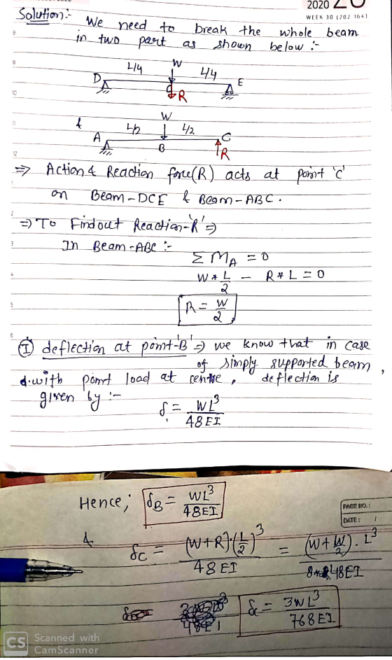
9. A beam ABC is simply supported on a rigid support at end A and on...
QUESTION 4 (25 marks) A simply supported beam is loaded by an uniform distributed load, wkN/m, over the span of the beam, L, as shown in Figure Q4. (a) Determine the end reactions at point A and...
 QUESTION 4 (25 marks) A simply supported beam is loaded by an uniform distributed load, wkN/m, over the span of the beam, L, as shown in Figure Q4. (a) Determine the end reactions at point A and B in terms of w and L. (4 marks) (b) At an arbitrary point, x, express the internal mom (c) Show that the deflection curve of the beam under the loading situation is ent, M(x), in x, w, and L. (5 marks) 24EI...
A 12 m beam is simply supported roller at one end, and hinged at the other...
 A 12 m beam is simply supported roller at one end, and hinged
at the other end. The beam has constant (EI) and the load on the
beam is illustrated as shown in Figure 1. Using the finite
difference method, determine deflections in the beam. Take h=∆x = ⁄
.
9. = 40 kN/m 50 mm 50 mm 6m Constant EIM 12 m Figure 1
A 12 m beam is simply supported roller at one end, and hinged
at the other end. The beam has constant (EI) and the load on the
beam is illustrated as shown in Figure 1. Using the finite
difference method, determine deflections in the beam. Take h=∆x = ⁄
.
9. = 40 kN/m 50 mm 50 mm 6m Constant EIM 12 m Figure 1
The simply supported beam AB in Figure 1 is subjected to a load variation given by...
 The simply supported beam AB in Figure 1 is subjected to a load variation given by w(x) = -kr". ܨܝ܂ Figure 1 (a) Determine the equation of the elastic curve in terms of El, x and L. (El is constant) (15 Points) (b) The beam has a length L of 1 m. Determine, in terms of k: (1) The reaction at the roller support. (3 Points) (ii) The bending moment at the section 0.2 m from end A, (that is,...
5) (20 pts) For the simply supported beam shown, find the appropriate W-section to support the lo...
 5) (20 pts) For the simply supported beam shown, find the appropriate W-section to support the loads. L- 15 ft, w 400 lb/ft, P 4000 lb, Ơallow = 36,000 lb/in2 L/2 L/2 wL/2 wL/2 Beam size-
5) (20 pts) For the simply supported beam shown, find the appropriate W-section to support the loads. L- 15 ft, w 400 lb/ft, P 4000 lb, Ơallow = 36,000 lb/in2 L/2 L/2 wL/2 wL/2 Beam size-
5) (20 pts) For the simply supported beam shown, find the appropriate W-section to support the loads. L- 15 ft, w 400 lb/ft, P 4000 lb, Ơallow = 36,000 lb/in2 L/2 L/2 wL/2 wL/2 Beam size-
A simply supported beam AB is subjected to a triangle loading (see figure). The moment curvature...
 A simply supported beam AB is subjected to a triangle loading (see figure). The moment curvature equation is shown (from the left). The (El-constant) 1. Determine the deflection at middle beam. 2. Determine the rotation at middle beam. 2 kN/m A B 4.m x3 EI dx2 = - 2 COM MacBook Air 20 COD F4 FS F6 ►II # $ دیا 4 % 5 6 & 7 8 9
A simply supported beam AB is subjected to a triangle loading (see figure). The moment curvature...
 A simply supported beam AB is subjected to a triangle loading (see figure). The moment curvature equation is shown (from the left). The (El-constant) 1. Determine the deflection at middle beam. 2. Determine the rotation at middle beam. 2 kN/m B 4 m 8 EI 12 MacBook Air DOO 008 A tA % A - 5 & 7 6 I 0 * 8 9 R T
A simply supported beam AB is subjected to a triangle loading (see figure). The moment curvature...
 A simply supported beam AB is subjected to a triangle loading (see figure). The moment curvature equation is shown (from the left). The (El=constant) 1. Determine the deflection at middle beam. 2. Determine the rotation at middle beam. 2 kN/m A B 4 m d2v x3 ΕΙ = dx? 12 -x2+1
A simply supported beam AB is subjected to a triangle loading (see figure). The moment curvature...
 A simply supported beam AB is subjected to a triangle loading (see figure). The moment curvature equation is shown (from the left). The (El=constant) 1. Determine the deflection at middle beam. 2. Determine the rotation at middle beam. 2 kN/m A B 4 m 8 d2v EI dx2 x3 12 *+z*
In Appendix C, see the simply supported beam with a uniformly distributed load. Be careful with...
 In Appendix C, see the simply supported beam with
a uniformly distributed load. Be careful with units and the sign
convention. For this calculation, the overhung part of the beam
from C to D can be ignored, and the beam is
treated as a simply supported beam of length
2L1. Be careful with units and the sign
convention.
The simply supported beam consists of a W530 × 66 structural steel
wide-flange shape [ E = 200 GPa; I = 351...
In Appendix C, see the simply supported beam with
a uniformly distributed load. Be careful with units and the sign
convention. For this calculation, the overhung part of the beam
from C to D can be ignored, and the beam is
treated as a simply supported beam of length
2L1. Be careful with units and the sign
convention.
The simply supported beam consists of a W530 × 66 structural steel
wide-flange shape [ E = 200 GPa; I = 351...
The steel beam ABCD shown in the figure is simply supported at Cand supported at Band...
 The steel beam ABCD shown in the figure is simply supported at Cand supported at Band D by shoulder steel bolts, each having a diameter of 10 mm. The lengths of BE and DF are 50 mm and 60 mm, respectively. The beam has a second area moment of 21 x 103 mm4. Prior to loading, the members are stress free. A force of P= 2000 N is then applied at point A. Using procedure 2 of Sec. 4– 10,...
 QUESTION 4 (25 marks) A simply supported beam is loaded by an uniform distributed load, wkN/m, over the span of the beam, L, as shown in Figure Q4. (a) Determine the end reactions at point A and B in terms of w and L. (4 marks) (b) At an arbitrary point, x, express the internal mom (c) Show that the deflection curve of the beam under the loading situation is ent, M(x), in x, w, and L. (5 marks) 24EI...
 A 12 m beam is simply supported roller at one end, and hinged
at the other end. The beam has constant (EI) and the load on the
beam is illustrated as shown in Figure 1. Using the finite
difference method, determine deflections in the beam. Take h=∆x = ⁄
.
9. = 40 kN/m 50 mm 50 mm 6m Constant EIM 12 m Figure 1
A 12 m beam is simply supported roller at one end, and hinged
at the other end. The beam has constant (EI) and the load on the
beam is illustrated as shown in Figure 1. Using the finite
difference method, determine deflections in the beam. Take h=∆x = ⁄
.
9. = 40 kN/m 50 mm 50 mm 6m Constant EIM 12 m Figure 1
 The simply supported beam AB in Figure 1 is subjected to a load variation given by w(x) = -kr". ܨܝ܂ Figure 1 (a) Determine the equation of the elastic curve in terms of El, x and L. (El is constant) (15 Points) (b) The beam has a length L of 1 m. Determine, in terms of k: (1) The reaction at the roller support. (3 Points) (ii) The bending moment at the section 0.2 m from end A, (that is,...
 5) (20 pts) For the simply supported beam shown, find the appropriate W-section to support the loads. L- 15 ft, w 400 lb/ft, P 4000 lb, Ơallow = 36,000 lb/in2 L/2 L/2 wL/2 wL/2 Beam size-
5) (20 pts) For the simply supported beam shown, find the appropriate W-section to support the loads. L- 15 ft, w 400 lb/ft, P 4000 lb, Ơallow = 36,000 lb/in2 L/2 L/2 wL/2 wL/2 Beam size-
5) (20 pts) For the simply supported beam shown, find the appropriate W-section to support the loads. L- 15 ft, w 400 lb/ft, P 4000 lb, Ơallow = 36,000 lb/in2 L/2 L/2 wL/2 wL/2 Beam size-
 A simply supported beam AB is subjected to a triangle loading (see figure). The moment curvature equation is shown (from the left). The (El-constant) 1. Determine the deflection at middle beam. 2. Determine the rotation at middle beam. 2 kN/m A B 4.m x3 EI dx2 = - 2 COM MacBook Air 20 COD F4 FS F6 ►II # $ دیا 4 % 5 6 & 7 8 9
 A simply supported beam AB is subjected to a triangle loading (see figure). The moment curvature equation is shown (from the left). The (El-constant) 1. Determine the deflection at middle beam. 2. Determine the rotation at middle beam. 2 kN/m B 4 m 8 EI 12 MacBook Air DOO 008 A tA % A - 5 & 7 6 I 0 * 8 9 R T
 A simply supported beam AB is subjected to a triangle loading (see figure). The moment curvature equation is shown (from the left). The (El=constant) 1. Determine the deflection at middle beam. 2. Determine the rotation at middle beam. 2 kN/m A B 4 m d2v x3 ΕΙ = dx? 12 -x2+1
 A simply supported beam AB is subjected to a triangle loading (see figure). The moment curvature equation is shown (from the left). The (El=constant) 1. Determine the deflection at middle beam. 2. Determine the rotation at middle beam. 2 kN/m A B 4 m 8 d2v EI dx2 x3 12 *+z*
 In Appendix C, see the simply supported beam with
a uniformly distributed load. Be careful with units and the sign
convention. For this calculation, the overhung part of the beam
from C to D can be ignored, and the beam is
treated as a simply supported beam of length
2L1. Be careful with units and the sign
convention.
The simply supported beam consists of a W530 × 66 structural steel
wide-flange shape [ E = 200 GPa; I = 351...
In Appendix C, see the simply supported beam with
a uniformly distributed load. Be careful with units and the sign
convention. For this calculation, the overhung part of the beam
from C to D can be ignored, and the beam is
treated as a simply supported beam of length
2L1. Be careful with units and the sign
convention.
The simply supported beam consists of a W530 × 66 structural steel
wide-flange shape [ E = 200 GPa; I = 351...
 The steel beam ABCD shown in the figure is simply supported at Cand supported at Band D by shoulder steel bolts, each having a diameter of 10 mm. The lengths of BE and DF are 50 mm and 60 mm, respectively. The beam has a second area moment of 21 x 103 mm4. Prior to loading, the members are stress free. A force of P= 2000 N is then applied at point A. Using procedure 2 of Sec. 4– 10,...
Most questions answered within 3 hours.
-
Where is the error in this code sequence?
String s1 = "Hello";
String s2 = "ello";...
asked 10 months ago -
Financial data for Joel de Paris, Inc., for last year
follow:
Joel de Paris, Inc.
Balance...
asked 10 months ago -
Consider this reaction:
Al2(SO4)3 (aq)+ BaCl3
(aq) Al2Cl6 (aq)- +
3BaSO4(s) . What is the...
asked 10 months ago -
Suppose that Savneet is considering increasing her
recent random sample from 20 car rentals to 40...
asked 10 months ago -
Trucks arrive at an unloading terminal at an average rate of 120
per hour.
Trucks arrive...
asked 10 months ago -
Why are methanol and ethanol completely soluble in water while
octanol is not very little soluble....
asked 10 months ago -
A facilities manager at a university reads in a research report
that the mean amount of...
asked 10 months ago -
When the CuSO4 is rehydrated by adding water to the anhydrous
compound, is this an endothermic...
asked 10 months ago -
A ray of sunlight is passing from diamond into crown glass; the
angle of incidence is...
asked 10 months ago -
A block of mass 0.249 kg is placed on top of a light, vertical
spring of...
asked 10 months ago -
how do the kidneys compensate in the presences of acidosis
a) trigger hyperventilate
b) reserve acid...
asked 10 months ago -
Question 501 pts
The rental rate of capital to the firm increases. Which of the
following...
asked 10 months ago