
Homework Answers

Add Answer to:
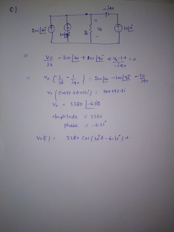
Chapter 16, Problem 16.025 Calculate vo(t) in the circuit shown in the figure below ifh(t) is...
Calculate vo(t) in the circuit shown in the figure below if i(t) is 200 cos(105t+ 60°) mA, i2(t) is 100 sin(105t90°) mA, and vst) 10 sin(105t) v uci) + 250 nF o(r) 52 Ohm Calculate vo(t) in the...
 Calculate vo(t) in the circuit shown in the figure below if i(t) is 200 cos(105t+ 60°) mA, i2(t) is 100 sin(105t90°) mA, and vst) 10 sin(105t) v uci) + 250 nF o(r) 52 Ohm
Calculate vo(t) in the circuit shown in the figure below if i(t) is 200 cos(105t+ 60°) mA, i2(t) is 100 sin(105t90°) mA, and vst) 10 sin(105t) v uci) + 250 nF o(r) 52 Ohm
Calculate vo(t) in the circuit shown in the figure below if i(t) is 200 cos(105t+ 60°) mA, i2(t) is 100 sin(105t90°) mA, and vst) 10 sin(105t) v uci) + 250 nF o(r) 52 Ohm
Chapter 8, Problem 8.025 Calculate v0(t) in the circuit shown in the figure below if i1(t)...
 Chapter 8, Problem 8.025
Calculate v0(t) in the
circuit shown in the figure below if
i1(t) is 200
cos(105t + 60o) mA,
i2(t) is 100
sin(105t + 90o) mA,and
vS(t) = 10
sin(105t) V.
Chapter 8, Problem 8.025
Calculate v0(t) in the
circuit shown in the figure below if
i1(t) is 200
cos(105t + 60o) mA,
i2(t) is 100
sin(105t + 90o) mA,and
vS(t) = 10
sin(105t) V.
Chapter 16, Problem 16.064 xIncorrect. Determine Vo in the circuit in the figure below. 2 1...
 Chapter 16, Problem 16.064 xIncorrect. Determine Vo in the circuit in the figure below. 2 1 2 j2? 2/0 A 2? Enter (a) the amplitude and (b) the phase angle. The phase angle must be in the interval (-180°, 180°] (a) T3.47 (b) TT-23 degrees
Chapter 8, Problem 8.133 Use Thévenin's theorem to find Vo in the network in the figure...
 Chapter 8, Problem 8.133 Use Thévenin's theorem to find Vo in the network in the figure below. Enter (a) the amplitude and (b) the phase angle. The phase angle must be in the interval (-180, 180°] degrees Click if you would like to Show Work for this question: Open Show Work
Chapter 16, Problem 16.050 Find Vo in the network in the figure below 2Ω 40Ω (a)...
 Chapter 16, Problem 16.050 Find Vo in the network in the figure below 2Ω 40Ω (a) Find the real part of vo (b) Find the imaginary part of Vo
Chapter 13, Problem 13.090 (Circuit Solution) Incorrect. Use source transformation to find Vo in the network...
 Chapter 13, Problem 13.090 (Circuit Solution) Incorrect. Use source transformation to find Vo in the network in the figure below 4 mA Vo =1116.807 the tolerance is +/-2% LINK TO TEXT
Chapter 16, Problem 16.049 (Circuit Solution) Incorrect Find the frequency-domain voltage Vo shown in the figure...
 Chapter 16, Problem 16.049 (Circuit Solution) Incorrect Find the frequency-domain voltage Vo shown in the figure below 15Ω 15Ω 5/30° A (a) Find the real part of the voltage. (b) Find the imaginary part of the voltage. (a) TT45.67 (b) T-18.12
Chapter 16, Problem 16.058 In the network in the figure below, Vo is known to be...
 Chapter 16, Problem 16.058 In the network in the figure below, Vo is known to be 4245. Find Z. 22 Ω (a) Find the real part of Z. b) Find the imaginary part of Z. Ohm Ohm
Chapter 8, Problem 8.097 (Circuit Solution) Find Vo in the network in the figure below. 12,60...
 Chapter 8, Problem 8.097 (Circuit Solution) Find Vo in the network in the figure below. 12,60 V (+ 2Ω 27 Ω 166 v 0° A (a) Find the real part of Vo (b) Find the imaginary part of Vo
14. Problem For the circuit in figure below, find the steady-state output voltage vo (t). The inp...
 14. Problem For the circuit in figure below, find the steady-state output voltage vo (t). The input signal is v (t) and C = 5 μF 4-2 cos 100t, R 1 kΩ Do C R 12 U)
14. Problem For the circuit in figure below, find the steady-state output voltage vo (t). The input signal is v (t) and C = 5 μF 4-2 cos 100t, R 1 kΩ Do C R 12 U)
14. Problem For the circuit in figure below, find the steady-state output voltage vo (t). The input signal is v (t) and C = 5 μF 4-2 cos 100t, R 1 kΩ Do C R 12 U)
 Calculate vo(t) in the circuit shown in the figure below if i(t) is 200 cos(105t+ 60°) mA, i2(t) is 100 sin(105t90°) mA, and vst) 10 sin(105t) v uci) + 250 nF o(r) 52 Ohm
Calculate vo(t) in the circuit shown in the figure below if i(t) is 200 cos(105t+ 60°) mA, i2(t) is 100 sin(105t90°) mA, and vst) 10 sin(105t) v uci) + 250 nF o(r) 52 Ohm
Calculate vo(t) in the circuit shown in the figure below if i(t) is 200 cos(105t+ 60°) mA, i2(t) is 100 sin(105t90°) mA, and vst) 10 sin(105t) v uci) + 250 nF o(r) 52 Ohm
 Chapter 8, Problem 8.025
Calculate v0(t) in the
circuit shown in the figure below if
i1(t) is 200
cos(105t + 60o) mA,
i2(t) is 100
sin(105t + 90o) mA,and
vS(t) = 10
sin(105t) V.
Chapter 8, Problem 8.025
Calculate v0(t) in the
circuit shown in the figure below if
i1(t) is 200
cos(105t + 60o) mA,
i2(t) is 100
sin(105t + 90o) mA,and
vS(t) = 10
sin(105t) V.
 Chapter 16, Problem 16.064 xIncorrect. Determine Vo in the circuit in the figure below. 2 1 2 j2? 2/0 A 2? Enter (a) the amplitude and (b) the phase angle. The phase angle must be in the interval (-180°, 180°] (a) T3.47 (b) TT-23 degrees
 Chapter 8, Problem 8.133 Use Thévenin's theorem to find Vo in the network in the figure below. Enter (a) the amplitude and (b) the phase angle. The phase angle must be in the interval (-180, 180°] degrees Click if you would like to Show Work for this question: Open Show Work
 Chapter 16, Problem 16.050 Find Vo in the network in the figure below 2Ω 40Ω (a) Find the real part of vo (b) Find the imaginary part of Vo
 Chapter 13, Problem 13.090 (Circuit Solution) Incorrect. Use source transformation to find Vo in the network in the figure below 4 mA Vo =1116.807 the tolerance is +/-2% LINK TO TEXT
 Chapter 16, Problem 16.049 (Circuit Solution) Incorrect Find the frequency-domain voltage Vo shown in the figure below 15Ω 15Ω 5/30° A (a) Find the real part of the voltage. (b) Find the imaginary part of the voltage. (a) TT45.67 (b) T-18.12
 Chapter 16, Problem 16.058 In the network in the figure below, Vo is known to be 4245. Find Z. 22 Ω (a) Find the real part of Z. b) Find the imaginary part of Z. Ohm Ohm
 Chapter 8, Problem 8.097 (Circuit Solution) Find Vo in the network in the figure below. 12,60 V (+ 2Ω 27 Ω 166 v 0° A (a) Find the real part of Vo (b) Find the imaginary part of Vo
 14. Problem For the circuit in figure below, find the steady-state output voltage vo (t). The input signal is v (t) and C = 5 μF 4-2 cos 100t, R 1 kΩ Do C R 12 U)
14. Problem For the circuit in figure below, find the steady-state output voltage vo (t). The input signal is v (t) and C = 5 μF 4-2 cos 100t, R 1 kΩ Do C R 12 U)
14. Problem For the circuit in figure below, find the steady-state output voltage vo (t). The input signal is v (t) and C = 5 μF 4-2 cos 100t, R 1 kΩ Do C R 12 U)
Most questions answered within 3 hours.
-
Where is the error in this code sequence?
String s1 = "Hello";
String s2 = "ello";...
asked 10 months ago -
Financial data for Joel de Paris, Inc., for last year
follow:
Joel de Paris, Inc.
Balance...
asked 10 months ago -
Consider this reaction:
Al2(SO4)3 (aq)+ BaCl3
(aq) Al2Cl6 (aq)- +
3BaSO4(s) . What is the...
asked 10 months ago -
Suppose that Savneet is considering increasing her
recent random sample from 20 car rentals to 40...
asked 10 months ago -
Trucks arrive at an unloading terminal at an average rate of 120
per hour.
Trucks arrive...
asked 10 months ago -
Why are methanol and ethanol completely soluble in water while
octanol is not very little soluble....
asked 10 months ago -
A facilities manager at a university reads in a research report
that the mean amount of...
asked 10 months ago -
When the CuSO4 is rehydrated by adding water to the anhydrous
compound, is this an endothermic...
asked 10 months ago -
A ray of sunlight is passing from diamond into crown glass; the
angle of incidence is...
asked 10 months ago -
A block of mass 0.249 kg is placed on top of a light, vertical
spring of...
asked 10 months ago -
how do the kidneys compensate in the presences of acidosis
a) trigger hyperventilate
b) reserve acid...
asked 10 months ago -
Question 501 pts
The rental rate of capital to the firm increases. Which of the
following...
asked 10 months ago