
Homework Answers


Add Answer to:
For the network shown in Figure 1. a) Find the impedances Zi. and Zc. (2 points)...
Review Part A. Find the relationship between the phasor voltage and phasor current for a resistance...
 Review Part A. Find the relationship between the phasor voltage and phasor current for a resistance The resistor shown here has been transformed into the phasor domain: Ik 4k Suppose that the phasor current is given by IR = 752120 mA. Find the phasor voltage VR. Enter a complex number in polar form, with phase angle in degrees. View Available Hint(s) 3002120 V Submit Previous Answers Correct Part B - Draw the phasor diagram of the resistance from Part A...
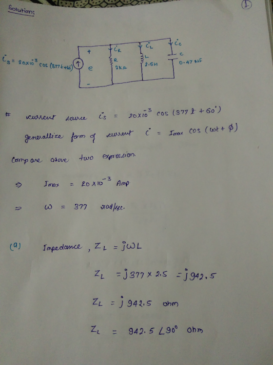
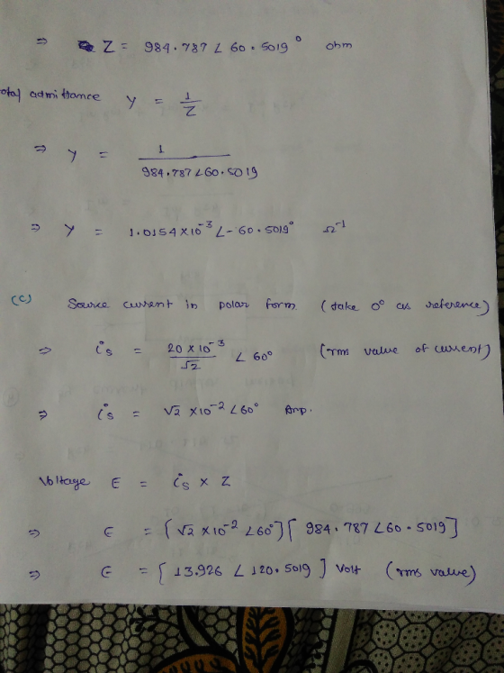
32. Repeat Problem 30 for the circuit of Fig. 15.141, replac- ing e with i, in part (d) IC e 35.4 sin(3141 +60) FIG. 15.141 Problem 32. a. Find the total admittance Yr in polar form. b. Draw the admi...
 32. Repeat Problem 30 for the circuit of Fig. 15.141, replac- ing e with i, in part (d) IC e 35.4 sin(3141 +60) FIG. 15.141 Problem 32. a. Find the total admittance Yr in polar form. b. Draw the admittance diagram. c. Find the value of C in microfarads and L in henries. d. Find the voltage E and currents Ie, l, and e in pha- sor form. e. Draw the phasor diagram of the currents Is, IR, I, and...
For the given circuit, a. Find the total admittance and impedance in polar form. b. Find...
 For the given circuit, a. Find the total admittance and impedance in polar form. b. Find the voltage E and currents I_r.I_L., and I_C in phasor form. c. Find the average power delivered to the circuit. d. Find the power factor and indicate if is leading or lagging. e. Find the time domain expressions for the currents and voltage. The total load on a 208 V, 60 Hz supply is 6 KW resistive, 10 kV AR inductive, and 4 kVAR...
8. Refer to the parallel network in Figure 1.18: (59.70 9.4 Calcu (3.685 9.5 Calca e(t) 325.27 si...
 8. Refer to the parallel network in Figure 1.18: (59.70 9.4 Calcu (3.685 9.5 Calca e(t) 325.27 sin (377t+ ) V I 1 16.45 A at a power factor of 0.8387 lagging 8.95 A at a power factor of 0.9063 I2 7.65 A at a power factor of 0.6428 9.6 Calo 8.1 8.2 8.3 8.4 Calculate the value of the components in each branch of the parallel circuit. (23.291 o; 244.224,F, ¡9.326 Ω; 61.09 mH: 3.68 Ω; 87.568 mH) Calculate...
Q2. A three-phase unbalanced delta-connected load containing impedances Z1, Z2 and resistor R3 is connected to...
 Q2. A three-phase unbalanced delta-connected load containing impedances Z1, Z2 and resistor R3 is connected to a three-phase power source of 380 V, 50 Hz in positive sequence A-B-C as shown in figure Q2. It is known that line current Ic is 54 292° A. The power consumption of load R3 is 18050 W. The impedance of Zi is 20 -70° 2. By taking VAB as reference, calculate B BB/ Z2 TBC figure Q2 (a) the line voltage VAB, VBC...
PLEASE! answer clearly and correctly!! Question VII In the Figure 7, find Vo v, = 4...
 PLEASE! answer clearly and correctly!!
Question VII In the Figure 7, find Vo v, = 4 cos( 1,000, ) V L=60mH C=12.5 μF Figure 7 QuestionI In Figure 1, l's s a sinusoidal signal in the form of Vin cos(wt + θ) V. Is RL Rc Vs Ic IL Figure 1 Find equivalent impedance seen by Vs . Assume: V, 10 cos( 1000t + π/4), RL-: 1009, Re-500Ω, L-0.1 H and C-50 μF - Find Is, I and Ic Find...
PLEASE! answer clearly and correctly!!
Question VII In the Figure 7, find Vo v, = 4 cos( 1,000, ) V L=60mH C=12.5 μF Figure 7 QuestionI In Figure 1, l's s a sinusoidal signal in the form of Vin cos(wt + θ) V. Is RL Rc Vs Ic IL Figure 1 Find equivalent impedance seen by Vs . Assume: V, 10 cos( 1000t + π/4), RL-: 1009, Re-500Ω, L-0.1 H and C-50 μF - Find Is, I and Ic Find...
3. For the circuit shown in Figure 1, + VR - R = 3k 494 ET...
 3. For the circuit shown in Figure 1, + VR - R = 3k 494 ET V 4.7 uF E = 8V sin(20,000t +60° -VL + Z = ? m L = 0.5 H Figure 1 i. ii. iv. v. vi. vii. Find the total impedance Zr in polar form. Draw the impedance diagram Find the current and the voltages VR, Vi and Vc in phasor form. Draw the phasor diagram of the voltages E, VR, V., and Vc and...
Based on a, only parts b, c, and d Due wrisis 1. Consider the circuit shown...
 Based on a, only parts b, c, and d
Due wrisis 1. Consider the circuit shown below ادا 0 WH)=-120ve sincrooof) R=150, c= 83.3 UF (rus) (a) Find the phosor representation of the voltage Note Trig Identity Sin10) = -cos( +90). V (+) = Vrasa cos(witte) u(t)=-120 va sin(1800€) V Vlt) 120v5 cosciroot t190) 20 290 V = 120490 v (6) Find the phasor, IR Virms) 120490 v= (C) Find the phasor, Ic Ica Army (d) Find the phaser, In...
Based on a, only parts b, c, and d
Due wrisis 1. Consider the circuit shown below ادا 0 WH)=-120ve sincrooof) R=150, c= 83.3 UF (rus) (a) Find the phosor representation of the voltage Note Trig Identity Sin10) = -cos( +90). V (+) = Vrasa cos(witte) u(t)=-120 va sin(1800€) V Vlt) 120v5 cosciroot t190) 20 290 V = 120490 v (6) Find the phasor, IR Virms) 120490 v= (C) Find the phasor, Ic Ica Army (d) Find the phaser, In...
Questions and answers are here, need solution process. 3. a) For the circuit shown in Figure...
 Questions and answers are here, need solution process.
3. a) For the circuit shown in Figure Q3 (a): i) Find the mathematical expression for the transient behaviour of the voltage 6 vc across the capacitor and the current ic when the switch is moved into position 1 at t- 0 s ii) Find the mathematical expression for the response of vc and ic if the switch 4 is moved into position 2 at t charging phase) τ (where τ is...
Questions and answers are here, need solution process.
3. a) For the circuit shown in Figure Q3 (a): i) Find the mathematical expression for the transient behaviour of the voltage 6 vc across the capacitor and the current ic when the switch is moved into position 1 at t- 0 s ii) Find the mathematical expression for the response of vc and ic if the switch 4 is moved into position 2 at t charging phase) τ (where τ is...
Consider the impedance diagram of a simple energy distribution network seen in fig. 1. The transmission...
 Consider the impedance diagram of a simple energy distribution network seen in fig. 1. The transmission lines that connect the buses have the line impedances as shown in the figure. The generators connected to buses 1 and 2 are known to be E1=1.0 pu (per unit) and E2=0.5 pu, respectively, on a 1 MV base. a) (05) Draw the admittance diagram for the system shown in fig. 1. b) (10) Obtain the bus admittance matrix Ybus for the system. c)...
 Review Part A. Find the relationship between the phasor voltage and phasor current for a resistance The resistor shown here has been transformed into the phasor domain: Ik 4k Suppose that the phasor current is given by IR = 752120 mA. Find the phasor voltage VR. Enter a complex number in polar form, with phase angle in degrees. View Available Hint(s) 3002120 V Submit Previous Answers Correct Part B - Draw the phasor diagram of the resistance from Part A...
 32. Repeat Problem 30 for the circuit of Fig. 15.141, replac- ing e with i, in part (d) IC e 35.4 sin(3141 +60) FIG. 15.141 Problem 32. a. Find the total admittance Yr in polar form. b. Draw the admittance diagram. c. Find the value of C in microfarads and L in henries. d. Find the voltage E and currents Ie, l, and e in pha- sor form. e. Draw the phasor diagram of the currents Is, IR, I, and...
 For the given circuit, a. Find the total admittance and impedance in polar form. b. Find the voltage E and currents I_r.I_L., and I_C in phasor form. c. Find the average power delivered to the circuit. d. Find the power factor and indicate if is leading or lagging. e. Find the time domain expressions for the currents and voltage. The total load on a 208 V, 60 Hz supply is 6 KW resistive, 10 kV AR inductive, and 4 kVAR...
 8. Refer to the parallel network in Figure 1.18: (59.70 9.4 Calcu (3.685 9.5 Calca e(t) 325.27 sin (377t+ ) V I 1 16.45 A at a power factor of 0.8387 lagging 8.95 A at a power factor of 0.9063 I2 7.65 A at a power factor of 0.6428 9.6 Calo 8.1 8.2 8.3 8.4 Calculate the value of the components in each branch of the parallel circuit. (23.291 o; 244.224,F, ¡9.326 Ω; 61.09 mH: 3.68 Ω; 87.568 mH) Calculate...
 Q2. A three-phase unbalanced delta-connected load containing impedances Z1, Z2 and resistor R3 is connected to a three-phase power source of 380 V, 50 Hz in positive sequence A-B-C as shown in figure Q2. It is known that line current Ic is 54 292° A. The power consumption of load R3 is 18050 W. The impedance of Zi is 20 -70° 2. By taking VAB as reference, calculate B BB/ Z2 TBC figure Q2 (a) the line voltage VAB, VBC...
 PLEASE! answer clearly and correctly!!
Question VII In the Figure 7, find Vo v, = 4 cos( 1,000, ) V L=60mH C=12.5 μF Figure 7 QuestionI In Figure 1, l's s a sinusoidal signal in the form of Vin cos(wt + θ) V. Is RL Rc Vs Ic IL Figure 1 Find equivalent impedance seen by Vs . Assume: V, 10 cos( 1000t + π/4), RL-: 1009, Re-500Ω, L-0.1 H and C-50 μF - Find Is, I and Ic Find...
PLEASE! answer clearly and correctly!!
Question VII In the Figure 7, find Vo v, = 4 cos( 1,000, ) V L=60mH C=12.5 μF Figure 7 QuestionI In Figure 1, l's s a sinusoidal signal in the form of Vin cos(wt + θ) V. Is RL Rc Vs Ic IL Figure 1 Find equivalent impedance seen by Vs . Assume: V, 10 cos( 1000t + π/4), RL-: 1009, Re-500Ω, L-0.1 H and C-50 μF - Find Is, I and Ic Find...
 3. For the circuit shown in Figure 1, + VR - R = 3k 494 ET V 4.7 uF E = 8V sin(20,000t +60° -VL + Z = ? m L = 0.5 H Figure 1 i. ii. iv. v. vi. vii. Find the total impedance Zr in polar form. Draw the impedance diagram Find the current and the voltages VR, Vi and Vc in phasor form. Draw the phasor diagram of the voltages E, VR, V., and Vc and...
 Based on a, only parts b, c, and d
Due wrisis 1. Consider the circuit shown below ادا 0 WH)=-120ve sincrooof) R=150, c= 83.3 UF (rus) (a) Find the phosor representation of the voltage Note Trig Identity Sin10) = -cos( +90). V (+) = Vrasa cos(witte) u(t)=-120 va sin(1800€) V Vlt) 120v5 cosciroot t190) 20 290 V = 120490 v (6) Find the phasor, IR Virms) 120490 v= (C) Find the phasor, Ic Ica Army (d) Find the phaser, In...
Based on a, only parts b, c, and d
Due wrisis 1. Consider the circuit shown below ادا 0 WH)=-120ve sincrooof) R=150, c= 83.3 UF (rus) (a) Find the phosor representation of the voltage Note Trig Identity Sin10) = -cos( +90). V (+) = Vrasa cos(witte) u(t)=-120 va sin(1800€) V Vlt) 120v5 cosciroot t190) 20 290 V = 120490 v (6) Find the phasor, IR Virms) 120490 v= (C) Find the phasor, Ic Ica Army (d) Find the phaser, In...
 Questions and answers are here, need solution process.
3. a) For the circuit shown in Figure Q3 (a): i) Find the mathematical expression for the transient behaviour of the voltage 6 vc across the capacitor and the current ic when the switch is moved into position 1 at t- 0 s ii) Find the mathematical expression for the response of vc and ic if the switch 4 is moved into position 2 at t charging phase) τ (where τ is...
Questions and answers are here, need solution process.
3. a) For the circuit shown in Figure Q3 (a): i) Find the mathematical expression for the transient behaviour of the voltage 6 vc across the capacitor and the current ic when the switch is moved into position 1 at t- 0 s ii) Find the mathematical expression for the response of vc and ic if the switch 4 is moved into position 2 at t charging phase) τ (where τ is...
 Consider the impedance diagram of a simple energy distribution network seen in fig. 1. The transmission lines that connect the buses have the line impedances as shown in the figure. The generators connected to buses 1 and 2 are known to be E1=1.0 pu (per unit) and E2=0.5 pu, respectively, on a 1 MV base. a) (05) Draw the admittance diagram for the system shown in fig. 1. b) (10) Obtain the bus admittance matrix Ybus for the system. c)...
Most questions answered within 3 hours.
-
Where is the error in this code sequence?
String s1 = "Hello";
String s2 = "ello";...
asked 10 months ago -
Financial data for Joel de Paris, Inc., for last year
follow:
Joel de Paris, Inc.
Balance...
asked 10 months ago -
Consider this reaction:
Al2(SO4)3 (aq)+ BaCl3
(aq) Al2Cl6 (aq)- +
3BaSO4(s) . What is the...
asked 10 months ago -
Suppose that Savneet is considering increasing her
recent random sample from 20 car rentals to 40...
asked 10 months ago -
Trucks arrive at an unloading terminal at an average rate of 120
per hour.
Trucks arrive...
asked 10 months ago -
Why are methanol and ethanol completely soluble in water while
octanol is not very little soluble....
asked 10 months ago -
A facilities manager at a university reads in a research report
that the mean amount of...
asked 10 months ago -
When the CuSO4 is rehydrated by adding water to the anhydrous
compound, is this an endothermic...
asked 10 months ago -
A ray of sunlight is passing from diamond into crown glass; the
angle of incidence is...
asked 10 months ago -
A block of mass 0.249 kg is placed on top of a light, vertical
spring of...
asked 10 months ago -
how do the kidneys compensate in the presences of acidosis
a) trigger hyperventilate
b) reserve acid...
asked 10 months ago -
Question 501 pts
The rental rate of capital to the firm increases. Which of the
following...
asked 10 months ago