
Homework Answers

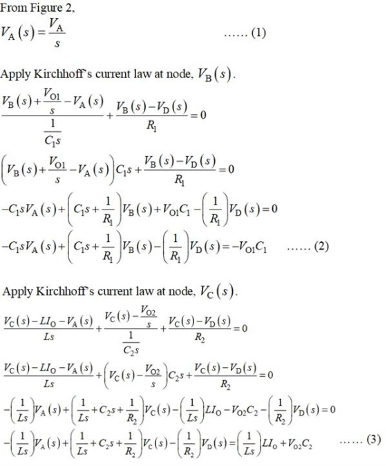


![Above four equation in matrix form as below [ 1 0 -48 Gs+ h (97 +Cos + Ls Vo(s)] IA LS + a Write the MATLAB code. >> clear al](http://img.homeworklib.com/questions/d9c8a380-b733-11ea-bd1a-d1edb34f2c02.png?x-oss-process=image/resize,w_560)
Add Answer to:
10-76 The circuit in Figure P10-76 is shown in the t domain with initial values for...
Circuit Analysis in the s-Domain 15.3. The initial voltage across the capacitor in the circuit shown in Figure P15.3 is v(0) 1 V, and the initial current through the inductor is i(0)0 mA Find th...
 Circuit Analysis in the s-Domain 15.3. The initial voltage across the capacitor in the circuit shown in Figure P15.3 is v(0) 1 V, and the initial current through the inductor is i(0)0 mA Find the voltage vo (t) across the capacitor for t 2 0 Figure P15.3 50 mH 1 kS2 V. Volt) T 0.1 μF The circuit in the s-domain is shown below. R2 Va 1k 0.05s 1/(sC)-1e7/s Vo R1 2k V (0-ys 5/s 1/s 1 format long; 2...
Problem 1 (20 points) You have the circuit shown below. 7 mA 8 kg %, 1...
 Problem 1 (20 points) You have the circuit shown below. 7 mA 8 kg %, 1 ko Rz 4k sht 10v ☺ ş 4 kg (lc Ako su sos a. Write a complete set of node voltage equations; one for each node (A through E) b. Using the equations from part a, determine the node voltages VA, VB, Vc, Vo and Ve c. Using the node voltages from part b, determine Vyand ly. Problem 2 (20 points) Using the same...
HW5 Problem 1 Creating Symbolic Expressions My Solutions > Problemi In the circuit below, the voltage...
 HW5 Problem 1 Creating Symbolic Expressions My Solutions > Problemi In the circuit below, the voltage source is given by v(t) = 12cos(400t - 30°). R1 = R2 = R3 = 51 and L1 = L2 = 20mH and C = mF. Please answer the following questions. w LI NL2 m i4 w un i3 R3 a) Transform the circuit into phasor domain b) Write out KCL for node N1 and N2 in the phasor domain c) Use KVL to...
For the time-domain circuit shown in Fig. 2 the switch is closed at t = 0....
 For the time-domain circuit shown in Fig. 2 the switch is closed
at t = 0.
a. Draw the equivalent circuit in s-domain.
b. Write a pair of simultaneous s-domain mesh current
equations.
2A * 4H 0.2 F 14v 149) 0.25 F 10 V izle G Fig. 2
For the time-domain circuit shown in Fig. 2 the switch is closed
at t = 0.
a. Draw the equivalent circuit in s-domain.
b. Write a pair of simultaneous s-domain mesh current
equations.
2A * 4H 0.2 F 14v 149) 0.25 F 10 V izle G Fig. 2
Name: Section: Jan. 31, 2018 1. Consider the circuit shown in figure 1 (a) Write the...
 Name: Section: Jan. 31, 2018 1. Consider the circuit shown in figure 1 (a) Write the mesh-current equations for the circuit. DO NOT SOLVE. (b) Write the node.voltage equations for the cireuit. DO NOT SOLVE 2. Consider the circuit shown in figure 2. The sinusoidal source is v,(04 sin (100t+90) volts (a) Transform the circuit to the frequency domain. (b) Use phasors with the mesh-current method to find the steady state expression for i(t). (c) Find the average power absorbed...
Problem 4.1 For the circuit shown in figure 4.1, there is no initial energy storage and v = 10u(t) V Please explain clearly! Thanks! Problem 4.1 2.5 H For the circuit shown in figure 4.1, there is no...
 Problem 4.1
For the circuit shown in figure 4.1, there is no initial energy
storage and v = 10u(t) V
Please explain clearly! Thanks!
Problem 4.1 2.5 H For the circuit shown in figure 4.1, there is no initial energy storage and v- 10 u(t) V (a) Obtain the circuit in the s-domain (b) Determine the current Los) (c) Determine for io(t) for t>0. 10Ω to 5 H 4 H Fig. 4.1
Problem 4.1 2.5 H For the circuit shown...
Problem 4.1
For the circuit shown in figure 4.1, there is no initial energy
storage and v = 10u(t) V
Please explain clearly! Thanks!
Problem 4.1 2.5 H For the circuit shown in figure 4.1, there is no initial energy storage and v- 10 u(t) V (a) Obtain the circuit in the s-domain (b) Determine the current Los) (c) Determine for io(t) for t>0. 10Ω to 5 H 4 H Fig. 4.1
Problem 4.1 2.5 H For the circuit shown...
8.43 The initial conditions for the circuit shown in Figure P8.43 are i(0) = 1 =...
 8.43 The initial conditions for the circuit shown in Figure P8.43 are i(0) = 1 = 1 A, v(0) = V. = 2 V. FIGURE P8.43 w 40 a. Write a node equation at node a by summing the currents leaving node a fort 20. Find di(0)/dt. b. Write a node equation at node b by summing the currents leaving node b for t 2 0. c. Find the differential equation in i(t) and find the roots of the characteristic...
PLEASE HELP! Jan. 31, 2018 Name: Section: I. Consider the circuit shown in figure (a) Write...
 PLEASE HELP!
Jan. 31, 2018 Name: Section: I. Consider the circuit shown in figure (a) Write the mesh-current equations (b) Write the for the circuit. D。~of SOL the circuit DO NOT SOLVE shown in figure 2. The sinusoidal source is the circuit to the frequency domain er the circuit (a) Transto with the mesh-current method to find thement (b) Use phasors with the mesh (c) Find the average power absorbed source is 、dt) = 2 sin (100t + 90") volts....
PLEASE HELP!
Jan. 31, 2018 Name: Section: I. Consider the circuit shown in figure (a) Write the mesh-current equations (b) Write the for the circuit. D。~of SOL the circuit DO NOT SOLVE shown in figure 2. The sinusoidal source is the circuit to the frequency domain er the circuit (a) Transto with the mesh-current method to find thement (b) Use phasors with the mesh (c) Find the average power absorbed source is 、dt) = 2 sin (100t + 90") volts....
Learning Goal: To use the node-voltage method to solve circuits with branches containing only a voltage...
 Learning Goal: To use the node-voltage method to solve circuits with branches containing only a voltage source. The node-voltage method is a general technique for solving circuits. Fundamentally, it involves writing KCL equations at essential nodes. When the circuit contains a dependent source, you must write a constraint equation for each dependent source, in addition to the KCL equations. When the circuit contains one or more voltage sources that are the only components in branches connecting two essential nodes, the...
In the circuit of Figure 2, find the initial and final values of the io (t)...
 In the circuit of Figure 2, find the initial and final values
of the io (t) current using the Laplace transform.
Şekil 1 Soru 2. (25 puan) Şekil 2'deki devrede io(t) akımının başlangıç ve nihai değerlerini Laplace dönüşümü kullanarak bulunuz? os w 1 = 0 1 = 0 103 10 V 1 F 320 4 A 1 H Şekil 2 Sinavin son teslim tarihi 07 Haziran 2020 Saat 04:00'dir. Zamanında yüklenmeyen/yüklenemeyen sınavın sorumluluğu inntalarini hatali ve vanlis icerik yükleme işleminden...
In the circuit of Figure 2, find the initial and final values
of the io (t) current using the Laplace transform.
Şekil 1 Soru 2. (25 puan) Şekil 2'deki devrede io(t) akımının başlangıç ve nihai değerlerini Laplace dönüşümü kullanarak bulunuz? os w 1 = 0 1 = 0 103 10 V 1 F 320 4 A 1 H Şekil 2 Sinavin son teslim tarihi 07 Haziran 2020 Saat 04:00'dir. Zamanında yüklenmeyen/yüklenemeyen sınavın sorumluluğu inntalarini hatali ve vanlis icerik yükleme işleminden...
 Circuit Analysis in the s-Domain 15.3. The initial voltage across the capacitor in the circuit shown in Figure P15.3 is v(0) 1 V, and the initial current through the inductor is i(0)0 mA Find the voltage vo (t) across the capacitor for t 2 0 Figure P15.3 50 mH 1 kS2 V. Volt) T 0.1 μF The circuit in the s-domain is shown below. R2 Va 1k 0.05s 1/(sC)-1e7/s Vo R1 2k V (0-ys 5/s 1/s 1 format long; 2...
 Problem 1 (20 points) You have the circuit shown below. 7 mA 8 kg %, 1 ko Rz 4k sht 10v ☺ ş 4 kg (lc Ako su sos a. Write a complete set of node voltage equations; one for each node (A through E) b. Using the equations from part a, determine the node voltages VA, VB, Vc, Vo and Ve c. Using the node voltages from part b, determine Vyand ly. Problem 2 (20 points) Using the same...
 HW5 Problem 1 Creating Symbolic Expressions My Solutions > Problemi In the circuit below, the voltage source is given by v(t) = 12cos(400t - 30°). R1 = R2 = R3 = 51 and L1 = L2 = 20mH and C = mF. Please answer the following questions. w LI NL2 m i4 w un i3 R3 a) Transform the circuit into phasor domain b) Write out KCL for node N1 and N2 in the phasor domain c) Use KVL to...
 For the time-domain circuit shown in Fig. 2 the switch is closed
at t = 0.
a. Draw the equivalent circuit in s-domain.
b. Write a pair of simultaneous s-domain mesh current
equations.
2A * 4H 0.2 F 14v 149) 0.25 F 10 V izle G Fig. 2
For the time-domain circuit shown in Fig. 2 the switch is closed
at t = 0.
a. Draw the equivalent circuit in s-domain.
b. Write a pair of simultaneous s-domain mesh current
equations.
2A * 4H 0.2 F 14v 149) 0.25 F 10 V izle G Fig. 2
 Name: Section: Jan. 31, 2018 1. Consider the circuit shown in figure 1 (a) Write the mesh-current equations for the circuit. DO NOT SOLVE. (b) Write the node.voltage equations for the cireuit. DO NOT SOLVE 2. Consider the circuit shown in figure 2. The sinusoidal source is v,(04 sin (100t+90) volts (a) Transform the circuit to the frequency domain. (b) Use phasors with the mesh-current method to find the steady state expression for i(t). (c) Find the average power absorbed...
 Problem 4.1
For the circuit shown in figure 4.1, there is no initial energy
storage and v = 10u(t) V
Please explain clearly! Thanks!
Problem 4.1 2.5 H For the circuit shown in figure 4.1, there is no initial energy storage and v- 10 u(t) V (a) Obtain the circuit in the s-domain (b) Determine the current Los) (c) Determine for io(t) for t>0. 10Ω to 5 H 4 H Fig. 4.1
Problem 4.1 2.5 H For the circuit shown...
Problem 4.1
For the circuit shown in figure 4.1, there is no initial energy
storage and v = 10u(t) V
Please explain clearly! Thanks!
Problem 4.1 2.5 H For the circuit shown in figure 4.1, there is no initial energy storage and v- 10 u(t) V (a) Obtain the circuit in the s-domain (b) Determine the current Los) (c) Determine for io(t) for t>0. 10Ω to 5 H 4 H Fig. 4.1
Problem 4.1 2.5 H For the circuit shown...
 8.43 The initial conditions for the circuit shown in Figure P8.43 are i(0) = 1 = 1 A, v(0) = V. = 2 V. FIGURE P8.43 w 40 a. Write a node equation at node a by summing the currents leaving node a fort 20. Find di(0)/dt. b. Write a node equation at node b by summing the currents leaving node b for t 2 0. c. Find the differential equation in i(t) and find the roots of the characteristic...
 PLEASE HELP!
Jan. 31, 2018 Name: Section: I. Consider the circuit shown in figure (a) Write the mesh-current equations (b) Write the for the circuit. D。~of SOL the circuit DO NOT SOLVE shown in figure 2. The sinusoidal source is the circuit to the frequency domain er the circuit (a) Transto with the mesh-current method to find thement (b) Use phasors with the mesh (c) Find the average power absorbed source is 、dt) = 2 sin (100t + 90") volts....
PLEASE HELP!
Jan. 31, 2018 Name: Section: I. Consider the circuit shown in figure (a) Write the mesh-current equations (b) Write the for the circuit. D。~of SOL the circuit DO NOT SOLVE shown in figure 2. The sinusoidal source is the circuit to the frequency domain er the circuit (a) Transto with the mesh-current method to find thement (b) Use phasors with the mesh (c) Find the average power absorbed source is 、dt) = 2 sin (100t + 90") volts....
 Learning Goal: To use the node-voltage method to solve circuits with branches containing only a voltage source. The node-voltage method is a general technique for solving circuits. Fundamentally, it involves writing KCL equations at essential nodes. When the circuit contains a dependent source, you must write a constraint equation for each dependent source, in addition to the KCL equations. When the circuit contains one or more voltage sources that are the only components in branches connecting two essential nodes, the...
 In the circuit of Figure 2, find the initial and final values
of the io (t) current using the Laplace transform.
Şekil 1 Soru 2. (25 puan) Şekil 2'deki devrede io(t) akımının başlangıç ve nihai değerlerini Laplace dönüşümü kullanarak bulunuz? os w 1 = 0 1 = 0 103 10 V 1 F 320 4 A 1 H Şekil 2 Sinavin son teslim tarihi 07 Haziran 2020 Saat 04:00'dir. Zamanında yüklenmeyen/yüklenemeyen sınavın sorumluluğu inntalarini hatali ve vanlis icerik yükleme işleminden...
In the circuit of Figure 2, find the initial and final values
of the io (t) current using the Laplace transform.
Şekil 1 Soru 2. (25 puan) Şekil 2'deki devrede io(t) akımının başlangıç ve nihai değerlerini Laplace dönüşümü kullanarak bulunuz? os w 1 = 0 1 = 0 103 10 V 1 F 320 4 A 1 H Şekil 2 Sinavin son teslim tarihi 07 Haziran 2020 Saat 04:00'dir. Zamanında yüklenmeyen/yüklenemeyen sınavın sorumluluğu inntalarini hatali ve vanlis icerik yükleme işleminden...
Most questions answered within 3 hours.
-
Where is the error in this code sequence?
String s1 = "Hello";
String s2 = "ello";...
asked 11 months ago -
Financial data for Joel de Paris, Inc., for last year
follow:
Joel de Paris, Inc.
Balance...
asked 11 months ago -
Consider this reaction:
Al2(SO4)3 (aq)+ BaCl3
(aq) Al2Cl6 (aq)- +
3BaSO4(s) . What is the...
asked 11 months ago -
Suppose that Savneet is considering increasing her
recent random sample from 20 car rentals to 40...
asked 11 months ago -
Trucks arrive at an unloading terminal at an average rate of 120
per hour.
Trucks arrive...
asked 11 months ago -
Why are methanol and ethanol completely soluble in water while
octanol is not very little soluble....
asked 11 months ago -
A facilities manager at a university reads in a research report
that the mean amount of...
asked 11 months ago -
When the CuSO4 is rehydrated by adding water to the anhydrous
compound, is this an endothermic...
asked 11 months ago -
A ray of sunlight is passing from diamond into crown glass; the
angle of incidence is...
asked 11 months ago -
A block of mass 0.249 kg is placed on top of a light, vertical
spring of...
asked 11 months ago -
how do the kidneys compensate in the presences of acidosis
a) trigger hyperventilate
b) reserve acid...
asked 11 months ago -
Question 501 pts
The rental rate of capital to the firm increases. Which of the
following...
asked 11 months ago