
Homework Answers
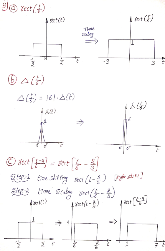
To sketch the given waveforms, we need to know the concept of time shifting and time scaling.
For more assistance please use comment section.
Add Answer to:
Sketch the below waveforms:
Question # 3) Sketch the below waveforms: a. rectG b. A c....
Answer both problems please. Problem 3: Accurately sketch the following function. Label all axes. 15 Points t - to...
 Answer both problems
please.
Problem 3: Accurately sketch the following function. Label all axes. 15 Points t - to W - to- 2W t - to - W x(t) =-B tri A rect - A rect W W t - t- 3W B tri /2 Problem 4: Accurately sketch the following function. Label all axes. 15 Points t - W t W 4 2T W x(t) = A rect A rect + B rect cos W W
Problem 3: Accurately...
Answer both problems
please.
Problem 3: Accurately sketch the following function. Label all axes. 15 Points t - to W - to- 2W t - to - W x(t) =-B tri A rect - A rect W W t - t- 3W B tri /2 Problem 4: Accurately sketch the following function. Label all axes. 15 Points t - W t W 4 2T W x(t) = A rect A rect + B rect cos W W
Problem 3: Accurately...
Nonsinusoidal Waveforms (pulse waveforms) A) Sketch two square waves, one with an average value of zero...
Nonsinusoidal Waveforms (pulse waveforms) A) Sketch two square waves, one with an average value of zero and one with an average value of 2 V. Label ALL pertinent amplitude and time quantities. B) Sketch two waveforms with the same duty cycle but different frequencies. Be sure to label all time and amplitude values.
1.On the graph below, make a neat and labeled sketch of the signal s(t) = 2...
1.On the graph below, make a neat and labeled sketch of the signal s(t) = 2 + cos( t/4 + 1 ),Describe s(t) as odd, even, or neither. What is the energy in s(t)? What is the power in s(t)? 2.On the graph below, make a neat and labeled sketch of the signal s(t) = 3 rect( t - 2 ) cos( π t ),Describe s(t) as odd, even, or neither. What is the energy in s(t)? What is the...
A) Write the mathematical expressions using the switching function for the waveforms below. B) Test your...
 A) Write the mathematical expressions using the switching function for the waveforms below. B) Test your expressions by plotting the waveforms from your expressions using mathematical software. (Include printouts with your homework.) X(t) 30+. 157 N 3 4 5 t[s] -30 1 2
2. Diode circuits and output waveforms. (a) Sketch the output waveforms expected when a 100Hz, 6V...
 2. Diode circuits and output waveforms. (a) Sketch the output waveforms expected when a 100Hz, 6Vp sine wave is applied to each of the circuits shown. Label important voltage levels and time values. Your plots should be large enough, at least 4 to 6 inches on a side, and semi-quantitative to represent accurately the output waveform. Note: the input signal is ap- plied to the left side of the circuit and the output taken from the two terminals on the...
Sketch the waveforms at Cp 20, 2', and 22 for 10 clock pulses for the 3-bit...
 Sketch the waveforms at Cp 20, 2', and 22 for 10 clock pulses for the 3-bit syn- chronous counter shown in Figure P6-27. 6-27. 2 Figure P6-27 The duty cycle of a square wave is defined as the time the wave is HIGH. divided by the total time for one period. From the waveforms that you sketched for Prob- lem 6-27, find the duty cycle for the 2' output wave. 6-28.
3. a. b. Apply the input waveforms (A,B,&C) of the following figure to a NOR gate,...
 3. a. b. Apply the input waveforms (A,B,&C) of the following figure to a NOR gate, & draw the output waveform. Repeat with C held permanently LOW. Repeat with C held HIGH. 10
3. Determine the following for the waveforms in Figure 4 given that each time division is...
 3. Determine the following for the waveforms in Figure 4 given that each time division is 5ms and each voltage division is 2V. a. peak voltages for each waveform b. period for both waveforms c. time delay, At, between vi() and v2(t). d. phase constant for v2(t)
Question #5: Consider the continuous-time signal shown below. x(t) -6 -4 -2 4 -2 (a) Sketch...
 Question #5: Consider the continuous-time signal shown below. x(t) -6 -4 -2 4 -2 (a) Sketch y(t) x1) (b) Sketch y(t) 2x[t- 2) (c) Sketch y(t) - 5x(t/3) (d) Sketch y(t) x(t) -x(-t)
 Answer both problems
please.
Problem 3: Accurately sketch the following function. Label all axes. 15 Points t - to W - to- 2W t - to - W x(t) =-B tri A rect - A rect W W t - t- 3W B tri /2 Problem 4: Accurately sketch the following function. Label all axes. 15 Points t - W t W 4 2T W x(t) = A rect A rect + B rect cos W W
Problem 3: Accurately...
Answer both problems
please.
Problem 3: Accurately sketch the following function. Label all axes. 15 Points t - to W - to- 2W t - to - W x(t) =-B tri A rect - A rect W W t - t- 3W B tri /2 Problem 4: Accurately sketch the following function. Label all axes. 15 Points t - W t W 4 2T W x(t) = A rect A rect + B rect cos W W
Problem 3: Accurately...
 A) Write the mathematical expressions using the switching function for the waveforms below. B) Test your expressions by plotting the waveforms from your expressions using mathematical software. (Include printouts with your homework.) X(t) 30+. 157 N 3 4 5 t[s] -30 1 2
 2. Diode circuits and output waveforms. (a) Sketch the output waveforms expected when a 100Hz, 6Vp sine wave is applied to each of the circuits shown. Label important voltage levels and time values. Your plots should be large enough, at least 4 to 6 inches on a side, and semi-quantitative to represent accurately the output waveform. Note: the input signal is ap- plied to the left side of the circuit and the output taken from the two terminals on the...
 Sketch the waveforms at Cp 20, 2', and 22 for 10 clock pulses for the 3-bit syn- chronous counter shown in Figure P6-27. 6-27. 2 Figure P6-27 The duty cycle of a square wave is defined as the time the wave is HIGH. divided by the total time for one period. From the waveforms that you sketched for Prob- lem 6-27, find the duty cycle for the 2' output wave. 6-28.
 3. a. b. Apply the input waveforms (A,B,&C) of the following figure to a NOR gate, & draw the output waveform. Repeat with C held permanently LOW. Repeat with C held HIGH. 10
 3. Determine the following for the waveforms in Figure 4 given that each time division is 5ms and each voltage division is 2V. a. peak voltages for each waveform b. period for both waveforms c. time delay, At, between vi() and v2(t). d. phase constant for v2(t)
 Question #5: Consider the continuous-time signal shown below. x(t) -6 -4 -2 4 -2 (a) Sketch y(t) x1) (b) Sketch y(t) 2x[t- 2) (c) Sketch y(t) - 5x(t/3) (d) Sketch y(t) x(t) -x(-t)
Most questions answered within 3 hours.
-
Where is the error in this code sequence?
String s1 = "Hello";
String s2 = "ello";...
asked 10 months ago -
Financial data for Joel de Paris, Inc., for last year
follow:
Joel de Paris, Inc.
Balance...
asked 10 months ago -
Consider this reaction:
Al2(SO4)3 (aq)+ BaCl3
(aq) Al2Cl6 (aq)- +
3BaSO4(s) . What is the...
asked 10 months ago -
Suppose that Savneet is considering increasing her
recent random sample from 20 car rentals to 40...
asked 10 months ago -
Trucks arrive at an unloading terminal at an average rate of 120
per hour.
Trucks arrive...
asked 10 months ago -
Why are methanol and ethanol completely soluble in water while
octanol is not very little soluble....
asked 10 months ago -
A facilities manager at a university reads in a research report
that the mean amount of...
asked 10 months ago -
When the CuSO4 is rehydrated by adding water to the anhydrous
compound, is this an endothermic...
asked 10 months ago -
A ray of sunlight is passing from diamond into crown glass; the
angle of incidence is...
asked 10 months ago -
A block of mass 0.249 kg is placed on top of a light, vertical
spring of...
asked 10 months ago -
how do the kidneys compensate in the presences of acidosis
a) trigger hyperventilate
b) reserve acid...
asked 10 months ago -
Question 501 pts
The rental rate of capital to the firm increases. Which of the
following...
asked 10 months ago