1. A sinusoidal current signal has amplitude of 10 amp and frequency of 60 Hz and...
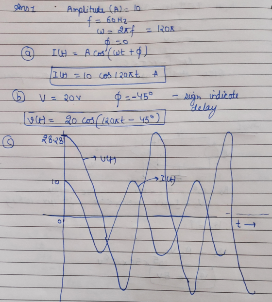
1. A sinusoidal current signal has amplitude of 10 amp and frequency of 60 Hz and phase angle of 0.
(a) Express the current in mathematical form.
(b) When it passes through an electric circuit, the voltage signal gets an amplitude of 20 volt and a phase delay of 45. Write the voltage signal.
(c) Draw both the voltage and current signals on the same graph.
2. Let a signal be defined as y(x) = (1 – x)2. Determine the following.
(a) Is the signal even or odd or have no symmetry?
(b) Find the even component of it and plot.
(c) Find the odd component of it and plot.
Homework Answers
Add Answer to:
1. A sinusoidal current signal has amplitude of 10 amp and
frequency of 60 Hz and...
2. Let a signal be defined as y(x) = (1 – x)2. Determine the following. (a)...
2. Let a signal be defined as y(x) = (1 – x)2. Determine the following. (a) Is the signal even or odd or have no symmetry? (b) Find the even component of it and plot. (c) Find the odd component of it and plot.
A 380 Hz sinusoidal voltage with a maximum amplitude of 120 V at t = 0 is applied across the terminals of an inductor.
A 380 Hz sinusoidal voltage with a maximum amplitude of 120 V at t = 0 is applied across the terminals of an inductor. The maximum amplitude of the steady-state current in the inductor is 20 A. Part A What is the frequency of the inductor current? Part B If the phase angle of the voltage is zero, what is the phase angle of the current? Part C What is the inductive reactance of the inductor? Part D What is the inductance of the inductor? Part E What is the...
Create a sinusoidal signal V(in) with the following parameters – VOFF = 10 + 2V, AMPLITUDE...
Create a sinusoidal signal V(in) with the following parameters – VOFF = 10 + 2V, AMPLITUDE = 3V, FREQUENCY= 500 Hz. Design a level shifting circuit such that the lower peak of V(in) is shifted to 5V, and the higher peak of V(in) is shifted to 0. Show by means of PSPICE Time Response simulation that your circuit really works. [Continue to use the two 9V batteries]. Make sure to explain every step in your design.
1. Sinusoidal signals The following sinusoidal diagram is the voltage across a "black box" and the...
 1. Sinusoidal signals The following sinusoidal diagram is the voltage across a "black box" and the current through it. The voltage and the current oscillate with the same frequency. a. Find the time period T, the natural frequency fand radial frequency o, Amplitude of the voltage and the current, the phase angle of the voltage and the current. (9 points) 200 current t/us t/us Current in mA lo T20 0 406 160.0 80.0 -200 20.0 voltage t/s Voltage in V...
a. An AC source of amplitude 10 Vmax and 500 Hz frequency is connected in series...
a. An AC source of amplitude 10 Vmax and 500 Hz frequency is connected in series with a 3 Kohm resistor and a 15 micro Farad capacitor. Draw the circuit. Determine the total current and the voltage drops across the resistor and the capacitor, respectively. b. An AC source of amplitude 10 Vmax and 5000 Hz frequency is connected in series with a 2 Kohm resistor and a 10 mH (milli Henry) inductor. Draw the circuit. Determine the total current...
a sinusoidal traveling transverse string wave with an amplitude of 5.5cm has a frequency of 10...
a sinusoidal traveling transverse string wave with an amplitude of 5.5cm has a frequency of 10 Hz and travels at 25m/s along the x axis.determine the maximum speed and determine the distance between the high and low spots on the string.
The maximal single-peak ECG signal amplitude can be approximately 10 mV and the frequency range of...
The maximal single-peak ECG signal amplitude can be approximately 10 mV and the frequency range of ECG signal is usually between 0.5-200 Hz. Design a one-op-amp band-pass filter circuit that will amplify the ECG to have the maximal gain possible without exceeding the typical guaranteed linear output range (±10V) and will pass the range of frequencies indicated (Assume Ri = 10 kΩ).
1-The period of oscillation of a sinusoidal signal is T=(95±3) ms. What is the uncertainty on...
1-The period of oscillation of a sinusoidal signal is T=(95±3) ms. What is the uncertainty on the frequency? (Report your value in Hz to 2 significant figures) 2-For a sinusoidal voltage waveform with amplitude A=(5.2±0.2) V, what is the error on the VRMS value? (Report your answer in V to 2 significant figures) 3-In an AC to DC rectifier circuit, the output DC signal of the rectified wave was measured to be VDC= (8.9±0.8)V and its ripple voltage was measured...
In this assignment, you will be working with two sinusoidal signals. The higher-frequency signal c(t)...
In this assignment, you will be working with two sinusoidal signals. The higher-frequency signal c(t) = cos(2*pi*F*t) (where F is in Hertz) will be referred to as "carrier"; while the lower-frequency signal v(t) = 1.5 + cos(2*pi*f*t + q) (f in Hz, again) will be referred to as "envelope". Note that the envelope has a positive offset of 1.5 units. In amplitude modulation (AM), the envelope multiplies the carrier and the resulting product signal is the AM...
130 V. For the following problems, A 60 Hz voltage source has an amplitude of VT...
 130 V. For the following problems, A 60 Hz voltage source has an amplitude of VT compute the indicated phasors l Q1. The source is connected across a series RL ac circuit with R = 8.2 Ohm and X1 = ω k = 5.7 Ohm. 1a) Find the magnitude of impedance of the series combination (Unit: Ohm) 1b) Find the phase angle of impedance of the series combination (Unit: dea) 1c) Calculate the current phasor I at an angle of...
 1. Sinusoidal signals The following sinusoidal diagram is the voltage across a "black box" and the current through it. The voltage and the current oscillate with the same frequency. a. Find the time period T, the natural frequency fand radial frequency o, Amplitude of the voltage and the current, the phase angle of the voltage and the current. (9 points) 200 current t/us t/us Current in mA lo T20 0 406 160.0 80.0 -200 20.0 voltage t/s Voltage in V...
 130 V. For the following problems, A 60 Hz voltage source has an amplitude of VT compute the indicated phasors l Q1. The source is connected across a series RL ac circuit with R = 8.2 Ohm and X1 = ω k = 5.7 Ohm. 1a) Find the magnitude of impedance of the series combination (Unit: Ohm) 1b) Find the phase angle of impedance of the series combination (Unit: dea) 1c) Calculate the current phasor I at an angle of...
Most questions answered within 3 hours.
-
Where is the error in this code sequence?
String s1 = "Hello";
String s2 = "ello";...
asked 11 months ago -
Financial data for Joel de Paris, Inc., for last year
follow:
Joel de Paris, Inc.
Balance...
asked 11 months ago -
Consider this reaction:
Al2(SO4)3 (aq)+ BaCl3
(aq) Al2Cl6 (aq)- +
3BaSO4(s) . What is the...
asked 11 months ago -
Suppose that Savneet is considering increasing her
recent random sample from 20 car rentals to 40...
asked 11 months ago -
Trucks arrive at an unloading terminal at an average rate of 120
per hour.
Trucks arrive...
asked 11 months ago -
Why are methanol and ethanol completely soluble in water while
octanol is not very little soluble....
asked 11 months ago -
A facilities manager at a university reads in a research report
that the mean amount of...
asked 11 months ago -
When the CuSO4 is rehydrated by adding water to the anhydrous
compound, is this an endothermic...
asked 11 months ago -
A ray of sunlight is passing from diamond into crown glass; the
angle of incidence is...
asked 11 months ago -
A block of mass 0.249 kg is placed on top of a light, vertical
spring of...
asked 11 months ago -
how do the kidneys compensate in the presences of acidosis
a) trigger hyperventilate
b) reserve acid...
asked 11 months ago -
Question 501 pts
The rental rate of capital to the firm increases. Which of the
following...
asked 11 months ago