
Homework Answers

Add Answer to:
8 Pr. 8 600 a)???eTransformer circuit shown above, as seen by tze Sourc Name 1?,res of...
3. The following measurements have been performed through the open-circuit test of a 15 kVA, 2300/230...
 3. The following measurements have been performed through the open-circuit test of a 15 kVA, 2300/230 V transformer: Voc 2300 V,loc 0.21 A, Poc 50 W, What parameters can be calculated through the open-circuit test of a transformer? Calculate the parameter values from the given data. (The equivalent circuit of a transformer is very similar to that of the induction motor shown above. The only differences are that there is no slip term's' and there is a resistance Rc representing...
Find the Thevenin Equivalent circuit for the circuit shown below as seen by the load resistor...
 Find the Thevenin Equivalent circuit for the circuit shown below as seen by the load resistor RL connected across terminals A and B. What is the maximum power can be absorbed by RL? [Sp2014 Exam 1] 5012 125V
Find the Norton equivalent circuit as seen from terminals a and b for the circuit shown...
 Find the Norton equivalent circuit as seen from terminals a and
b for the circuit shown in Figure 1.
Norton resistance (Ra-b) Blank 1, kiloohms
Norton current (Ia-b) Blank 2, mA
Vo 20KQ 10kn a 12V 6Vo b Figure
Find the Norton equivalent circuit as seen from terminals a and
b for the circuit shown in Figure 1.
Norton resistance (Ra-b) Blank 1, kiloohms
Norton current (Ia-b) Blank 2, mA
Vo 20KQ 10kn a 12V 6Vo b Figure
Problem 1 hv 1k 8 mA 5mA sk (a) Analyze the circuit shown above using nodal...
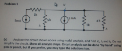 Problem 1 hv 1k 8 mA 5mA sk (a) Analyze the circuit shown above using nodal analysis, and find V, 1 and 12. Do not simplify the circuit. Show all analysis steps. Circuit analysis can be done "by hand" using! pen or pencil, but if you prefer, you may type the solutions too.
2.120 pts] A schematic diagram of transformer is shown below. The closed path, l in the magnetic circuit in the Figure is traced by magnetic flux Ф. N,, N2, and 11, 12 are the numbers of turns and th...
 2.120 pts] A schematic diagram of transformer is shown below. The closed path, l in the magnetic circuit in the Figure is traced by magnetic flux Ф. N,, N2, and 11, 12 are the numbers of turns and the currents in the primary and secondary circuits, respectively. The permeability, and cross-section of ferromagnetic core is, u and A İl(r) (a) [6 pts] Draw an equivalent magnetic circuit with two magnetomotive force, Vmmfi, and Vmmf2, magnetic closed flux, 4, and magnetic...
Determine the equivalent capacitance seen by the source in the circuit shown. Assume C5 = 2...
 Determine the equivalent capacitance seen by the source in the circuit shown. Assume C5 = 2 MF, C6 = 1 uF, C7 = 3 MF, Cg = 4 uF. 11 = sine 1 kHz 65 The equivalent capacitance seen by the source is MF. (Round the final answer to two decimal places.)
Find the Norton equivalent circuit as seen from terminals a and b for the circuit shown...
 Find the Norton equivalent circuit as seen from terminals a and
b for the circuit shown in Figure 1.
Norton resistance (Ra-b) Blank 1, kiloohms
Norton current (Ia-b) Blank 2, mA
a 3kQ 10k 2 + 70V 250 0.01V. Y >5kQ Figure 3
Find the Norton equivalent circuit as seen from terminals a and
b for the circuit shown in Figure 1.
Norton resistance (Ra-b) Blank 1, kiloohms
Norton current (Ia-b) Blank 2, mA
a 3kQ 10k 2 + 70V 250 0.01V. Y >5kQ Figure 3
Name: Section: Jan. 31, 2018 1. Consider the circuit shown in figure 1 (a) Write the...
 Name: Section: Jan. 31, 2018 1. Consider the circuit shown in figure 1 (a) Write the mesh-current equations for the circuit. DO NOT SOLVE. (b) Write the node.voltage equations for the cireuit. DO NOT SOLVE 2. Consider the circuit shown in figure 2. The sinusoidal source is v,(04 sin (100t+90) volts (a) Transform the circuit to the frequency domain. (b) Use phasors with the mesh-current method to find the steady state expression for i(t). (c) Find the average power absorbed...
Pr. #1) In computer graphics and perspective drawing, we need to represent objects seen by the...
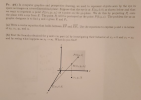 Pr. #1) In computer graphics and perspective drawing, we need to represent objects seen by the eye in space as images on a two-dimensional plano. Suppose that the west 0.01) as shown below and that we want to represent a point ( V ) as a point on the plane. We do this by projecting Ponto the plane with a ray from E. The point will be portrayed as the point P(0.y.). The problem for us as graphic designers is...
4. For the circuit shown, compute the voltage across the load terminals 0.10 j0.5Ω 1-600"A 1200...
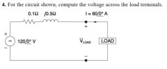 4. For the circuit shown, compute the voltage across the load terminals 0.10 j0.5Ω 1-600"A 1200 V VLOAD LOAD
 3. The following measurements have been performed through the open-circuit test of a 15 kVA, 2300/230 V transformer: Voc 2300 V,loc 0.21 A, Poc 50 W, What parameters can be calculated through the open-circuit test of a transformer? Calculate the parameter values from the given data. (The equivalent circuit of a transformer is very similar to that of the induction motor shown above. The only differences are that there is no slip term's' and there is a resistance Rc representing...
 Find the Thevenin Equivalent circuit for the circuit shown below as seen by the load resistor RL connected across terminals A and B. What is the maximum power can be absorbed by RL? [Sp2014 Exam 1] 5012 125V
 Find the Norton equivalent circuit as seen from terminals a and
b for the circuit shown in Figure 1.
Norton resistance (Ra-b) Blank 1, kiloohms
Norton current (Ia-b) Blank 2, mA
Vo 20KQ 10kn a 12V 6Vo b Figure
Find the Norton equivalent circuit as seen from terminals a and
b for the circuit shown in Figure 1.
Norton resistance (Ra-b) Blank 1, kiloohms
Norton current (Ia-b) Blank 2, mA
Vo 20KQ 10kn a 12V 6Vo b Figure
 Problem 1 hv 1k 8 mA 5mA sk (a) Analyze the circuit shown above using nodal analysis, and find V, 1 and 12. Do not simplify the circuit. Show all analysis steps. Circuit analysis can be done "by hand" using! pen or pencil, but if you prefer, you may type the solutions too.
 2.120 pts] A schematic diagram of transformer is shown below. The closed path, l in the magnetic circuit in the Figure is traced by magnetic flux Ф. N,, N2, and 11, 12 are the numbers of turns and the currents in the primary and secondary circuits, respectively. The permeability, and cross-section of ferromagnetic core is, u and A İl(r) (a) [6 pts] Draw an equivalent magnetic circuit with two magnetomotive force, Vmmfi, and Vmmf2, magnetic closed flux, 4, and magnetic...
 Determine the equivalent capacitance seen by the source in the circuit shown. Assume C5 = 2 MF, C6 = 1 uF, C7 = 3 MF, Cg = 4 uF. 11 = sine 1 kHz 65 The equivalent capacitance seen by the source is MF. (Round the final answer to two decimal places.)
 Find the Norton equivalent circuit as seen from terminals a and
b for the circuit shown in Figure 1.
Norton resistance (Ra-b) Blank 1, kiloohms
Norton current (Ia-b) Blank 2, mA
a 3kQ 10k 2 + 70V 250 0.01V. Y >5kQ Figure 3
Find the Norton equivalent circuit as seen from terminals a and
b for the circuit shown in Figure 1.
Norton resistance (Ra-b) Blank 1, kiloohms
Norton current (Ia-b) Blank 2, mA
a 3kQ 10k 2 + 70V 250 0.01V. Y >5kQ Figure 3
 Name: Section: Jan. 31, 2018 1. Consider the circuit shown in figure 1 (a) Write the mesh-current equations for the circuit. DO NOT SOLVE. (b) Write the node.voltage equations for the cireuit. DO NOT SOLVE 2. Consider the circuit shown in figure 2. The sinusoidal source is v,(04 sin (100t+90) volts (a) Transform the circuit to the frequency domain. (b) Use phasors with the mesh-current method to find the steady state expression for i(t). (c) Find the average power absorbed...
 Pr. #1) In computer graphics and perspective drawing, we need to represent objects seen by the eye in space as images on a two-dimensional plano. Suppose that the west 0.01) as shown below and that we want to represent a point ( V ) as a point on the plane. We do this by projecting Ponto the plane with a ray from E. The point will be portrayed as the point P(0.y.). The problem for us as graphic designers is...
 4. For the circuit shown, compute the voltage across the load terminals 0.10 j0.5Ω 1-600"A 1200 V VLOAD LOAD
Most questions answered within 3 hours.
-
Where is the error in this code sequence?
String s1 = "Hello";
String s2 = "ello";...
asked 11 months ago -
Financial data for Joel de Paris, Inc., for last year
follow:
Joel de Paris, Inc.
Balance...
asked 11 months ago -
Consider this reaction:
Al2(SO4)3 (aq)+ BaCl3
(aq) Al2Cl6 (aq)- +
3BaSO4(s) . What is the...
asked 11 months ago -
Suppose that Savneet is considering increasing her
recent random sample from 20 car rentals to 40...
asked 11 months ago -
Trucks arrive at an unloading terminal at an average rate of 120
per hour.
Trucks arrive...
asked 11 months ago -
Why are methanol and ethanol completely soluble in water while
octanol is not very little soluble....
asked 11 months ago -
A facilities manager at a university reads in a research report
that the mean amount of...
asked 11 months ago -
When the CuSO4 is rehydrated by adding water to the anhydrous
compound, is this an endothermic...
asked 11 months ago -
A ray of sunlight is passing from diamond into crown glass; the
angle of incidence is...
asked 11 months ago -
A block of mass 0.249 kg is placed on top of a light, vertical
spring of...
asked 11 months ago -
how do the kidneys compensate in the presences of acidosis
a) trigger hyperventilate
b) reserve acid...
asked 11 months ago -
Question 501 pts
The rental rate of capital to the firm increases. Which of the
following...
asked 11 months ago