

Homework Answers

Add Answer to:
Question 3. The bandpass filter in Figure 2 with input vi and output vo has a...
The center frequency is not given. I believe that it must be find based on the body plot. Problem 6:The Bode plot for a passive series RLC bandpass filter is shown in Fig. 2. This filter was built...
 The center frequency is not given. I believe that it must be
find based on the body plot.
Problem 6:The Bode plot for a passive series RLC bandpass filter is shown in Fig. 2. This filter was built from a 10 μ F capacitor. What is the filter's center frequency, wo, and its quality factor,昱? If you wanted to double the filter's center frequency without changing its quality factor, using the same 10 pu F capacitor, then how would you...
The center frequency is not given. I believe that it must be
find based on the body plot.
Problem 6:The Bode plot for a passive series RLC bandpass filter is shown in Fig. 2. This filter was built from a 10 μ F capacitor. What is the filter's center frequency, wo, and its quality factor,昱? If you wanted to double the filter's center frequency without changing its quality factor, using the same 10 pu F capacitor, then how would you...
Consider the series RLC bandpass filter shown in (Figure 1). The filter has a quality of...
 Consider the series RLC bandpass filter shown in (Figure 1). The filter has a quality of 2 and a center frequency of 8 kHz. The input to the filter is vi (t) = 23 cos wt V. Suppose that C = 5 nF. Figure < 1 of 1 + VLC с L HE + + Vi R} R V. Part E Find the voltage drop across the series combination of the inductor and capacitor when w=10w, Suppose that vlc (t)...
21 Vi Z2 Vo Figure 1 1. Ref: Figure 1. Let Z1 L (an inductor), Z2 - R (a resistor). Vi Calculate the magnitude and phase of the transfer function H(w) Figure 1 T 2. Repeat #1 with L = 100 mH, R 1kΩ....
 21 Vi Z2 Vo Figure 1 1. Ref: Figure 1. Let Z1 L (an inductor), Z2 - R (a resistor). Vi Calculate the magnitude and phase of the transfer function H(w) Figure 1 T 2. Repeat #1 with L = 100 mH, R 1kΩ. a) Plot the frequency response in dB* on a both on a linear scale and then a log scale from ω-1 to 100,000,000 rad/sec with points every decade (1 b) 1,000 etc). 10 100 Plot the...
Question 1 (15 points) Consider the circuit below with vi as the input and v, as...
 Question 1 (15 points) Consider the circuit below with vi as the input and v, as the output. Let the component values be R = 1001 and C = 1000F. C + v;(t) vo(t) Answer the following questions using the formulas from the lecture slides: 1. What is the type of this filter? (1 points) 2. Write down the expression for the transfer function H(w) of the circuit. (4 points) 3. Write down the expression for frequency response |H(w) of...
Problem 14.18 PSpice Multisim Part C Find Q For the bandpass filter shown the fiqure R 9 kSn,C 8 ...
 Problem 14.18 PSpice Multisim Part C Find Q For the bandpass filter shown the fiqure R 9 kSn,C 8 nF , and L = 12mH (Figure 1) vec Q0.136083 Figure 1 of 1> SubmitPre ious Ans Request Answer X Incorrect; Try Again; 3 attempts remaining ▼ Part D Find wel vec krad/s cl Problem 14.18 PSpice Multisim Part E k2, C 8 For the bandpass filter shown the figure R nF, and L 12 mHH (Figure 1) 9 Find fal...
(14%) 6. Consider an FM modulator with output )-100 cos(2(1000)r+(0) The modulator operates with fa = 8 and has the input message signal The modulator is followed by a bandpass filter with a...
 (14%) 6. Consider an FM modulator with output )-100 cos(2(1000)r+(0) The modulator operates with fa = 8 and has the input message signal The modulator is followed by a bandpass filter with a a bandwidth of 56HZ, as shown in the following figure. Determine the power ratio and the power at the fiter oput center frequency of 1000HZ and Bandpass filter PM Output Center 1000 Hz Bandwidth 56 Hz mt-5 cos 2(8)r modulator -1000 Hz (a) FM system 39.1 39.1365...
3.2 Simple Bandpass Filter Design The L-point averaging filter is a lowpass filter. Its passband width...
 3.2 Simple Bandpass Filter Design The L-point averaging filter is a lowpass filter. Its passband width is controlled by L, being inversely proportional to L. In fact, you can use the GUI altidemo to view the frequency response for different averagers and measure the passband widths. It is also possible to create a filter whose passband is centered around some frequency other than zero. One simple way to do this is to define the impulse response of an L-point FIR...
C1 Problem 2. Active Filter For the active filter shown in the figure a) Write the...
 C1 Problem 2. Active Filter For the active filter shown in the figure a) Write the node equations by taking Laplace Transform 1/G 1/G oVolt) of the circuit first. Then simplify the equations and write your final answer in matrix form. 2 b) Find the transfer function from Vi(s) to Vo(s). Simplify it properly (the denominator should be monic) Note: Using the conductance G-1/R leads to simpler equations.
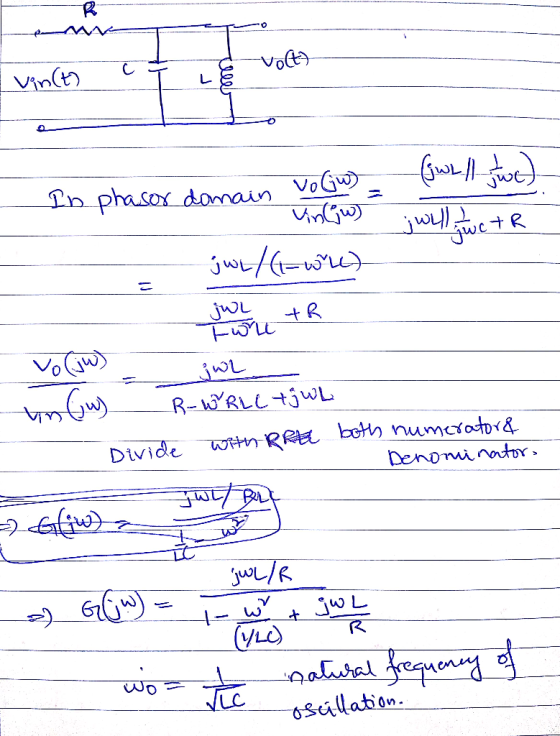
The transfer function Vo(s)/Vi(s) of the electrical system described in figure shown below is: * (3...
 The transfer function Vo(s)/Vi(s) of the electrical system described in figure shown below is: * (3 Points) R w + U L 10000 Vo (LCS"3(LC S) 12+ CR 5+1) 1/(LC s 2+ CR S+1) Ayat Abdullah Muham posted a new messag Automatic Control 110005 Ls/(C 2+ CR 5+1) 2. CR 5+1)Option 6
Please answer clearly Question 2 The amplifier shown in Figure 2 has the following parameters: Kn(W/L)-1 mA/V2, V-1 V Determine a) Voltage gain (Vo/vi) b) Input resistance (R) c) Output resistance (R...
 Please answer clearly
Question 2 The amplifier shown in Figure 2 has the following parameters: Kn(W/L)-1 mA/V2, V-1 V Determine a) Voltage gain (Vo/vi) b) Input resistance (R) c) Output resistance (Ro) d) Maximum output voltage swing so as the amplifier stays in saturation mode. Assume VDD-20 V, R1-2.5 ΚΩ, R2-1KQ, R3-0.5 ΚΩ, R4-5 MQ, R5_1ΜΩ. R4 R1 R5 R2 Ro R3
Question 2 The amplifier shown in Figure 2 has the following parameters: Kn(W/L)-1 mA/V2, V-1 V Determine a)...
Please answer clearly
Question 2 The amplifier shown in Figure 2 has the following parameters: Kn(W/L)-1 mA/V2, V-1 V Determine a) Voltage gain (Vo/vi) b) Input resistance (R) c) Output resistance (Ro) d) Maximum output voltage swing so as the amplifier stays in saturation mode. Assume VDD-20 V, R1-2.5 ΚΩ, R2-1KQ, R3-0.5 ΚΩ, R4-5 MQ, R5_1ΜΩ. R4 R1 R5 R2 Ro R3
Question 2 The amplifier shown in Figure 2 has the following parameters: Kn(W/L)-1 mA/V2, V-1 V Determine a)...
 The center frequency is not given. I believe that it must be
find based on the body plot.
Problem 6:The Bode plot for a passive series RLC bandpass filter is shown in Fig. 2. This filter was built from a 10 μ F capacitor. What is the filter's center frequency, wo, and its quality factor,昱? If you wanted to double the filter's center frequency without changing its quality factor, using the same 10 pu F capacitor, then how would you...
The center frequency is not given. I believe that it must be
find based on the body plot.
Problem 6:The Bode plot for a passive series RLC bandpass filter is shown in Fig. 2. This filter was built from a 10 μ F capacitor. What is the filter's center frequency, wo, and its quality factor,昱? If you wanted to double the filter's center frequency without changing its quality factor, using the same 10 pu F capacitor, then how would you...
 Consider the series RLC bandpass filter shown in (Figure 1). The filter has a quality of 2 and a center frequency of 8 kHz. The input to the filter is vi (t) = 23 cos wt V. Suppose that C = 5 nF. Figure < 1 of 1 + VLC с L HE + + Vi R} R V. Part E Find the voltage drop across the series combination of the inductor and capacitor when w=10w, Suppose that vlc (t)...
 21 Vi Z2 Vo Figure 1 1. Ref: Figure 1. Let Z1 L (an inductor), Z2 - R (a resistor). Vi Calculate the magnitude and phase of the transfer function H(w) Figure 1 T 2. Repeat #1 with L = 100 mH, R 1kΩ. a) Plot the frequency response in dB* on a both on a linear scale and then a log scale from ω-1 to 100,000,000 rad/sec with points every decade (1 b) 1,000 etc). 10 100 Plot the...
 Question 1 (15 points) Consider the circuit below with vi as the input and v, as the output. Let the component values be R = 1001 and C = 1000F. C + v;(t) vo(t) Answer the following questions using the formulas from the lecture slides: 1. What is the type of this filter? (1 points) 2. Write down the expression for the transfer function H(w) of the circuit. (4 points) 3. Write down the expression for frequency response |H(w) of...
 Problem 14.18 PSpice Multisim Part C Find Q For the bandpass filter shown the fiqure R 9 kSn,C 8 nF , and L = 12mH (Figure 1) vec Q0.136083 Figure 1 of 1> SubmitPre ious Ans Request Answer X Incorrect; Try Again; 3 attempts remaining ▼ Part D Find wel vec krad/s cl Problem 14.18 PSpice Multisim Part E k2, C 8 For the bandpass filter shown the figure R nF, and L 12 mHH (Figure 1) 9 Find fal...
 (14%) 6. Consider an FM modulator with output )-100 cos(2(1000)r+(0) The modulator operates with fa = 8 and has the input message signal The modulator is followed by a bandpass filter with a a bandwidth of 56HZ, as shown in the following figure. Determine the power ratio and the power at the fiter oput center frequency of 1000HZ and Bandpass filter PM Output Center 1000 Hz Bandwidth 56 Hz mt-5 cos 2(8)r modulator -1000 Hz (a) FM system 39.1 39.1365...
 3.2 Simple Bandpass Filter Design The L-point averaging filter is a lowpass filter. Its passband width is controlled by L, being inversely proportional to L. In fact, you can use the GUI altidemo to view the frequency response for different averagers and measure the passband widths. It is also possible to create a filter whose passband is centered around some frequency other than zero. One simple way to do this is to define the impulse response of an L-point FIR...
 C1 Problem 2. Active Filter For the active filter shown in the figure a) Write the node equations by taking Laplace Transform 1/G 1/G oVolt) of the circuit first. Then simplify the equations and write your final answer in matrix form. 2 b) Find the transfer function from Vi(s) to Vo(s). Simplify it properly (the denominator should be monic) Note: Using the conductance G-1/R leads to simpler equations.
 The transfer function Vo(s)/Vi(s) of the electrical system described in figure shown below is: * (3 Points) R w + U L 10000 Vo (LCS"3(LC S) 12+ CR 5+1) 1/(LC s 2+ CR S+1) Ayat Abdullah Muham posted a new messag Automatic Control 110005 Ls/(C 2+ CR 5+1) 2. CR 5+1)Option 6
 Please answer clearly
Question 2 The amplifier shown in Figure 2 has the following parameters: Kn(W/L)-1 mA/V2, V-1 V Determine a) Voltage gain (Vo/vi) b) Input resistance (R) c) Output resistance (Ro) d) Maximum output voltage swing so as the amplifier stays in saturation mode. Assume VDD-20 V, R1-2.5 ΚΩ, R2-1KQ, R3-0.5 ΚΩ, R4-5 MQ, R5_1ΜΩ. R4 R1 R5 R2 Ro R3
Question 2 The amplifier shown in Figure 2 has the following parameters: Kn(W/L)-1 mA/V2, V-1 V Determine a)...
Please answer clearly
Question 2 The amplifier shown in Figure 2 has the following parameters: Kn(W/L)-1 mA/V2, V-1 V Determine a) Voltage gain (Vo/vi) b) Input resistance (R) c) Output resistance (Ro) d) Maximum output voltage swing so as the amplifier stays in saturation mode. Assume VDD-20 V, R1-2.5 ΚΩ, R2-1KQ, R3-0.5 ΚΩ, R4-5 MQ, R5_1ΜΩ. R4 R1 R5 R2 Ro R3
Question 2 The amplifier shown in Figure 2 has the following parameters: Kn(W/L)-1 mA/V2, V-1 V Determine a)...
Most questions answered within 3 hours.
-
Where is the error in this code sequence?
String s1 = "Hello";
String s2 = "ello";...
asked 10 months ago -
Financial data for Joel de Paris, Inc., for last year
follow:
Joel de Paris, Inc.
Balance...
asked 10 months ago -
Consider this reaction:
Al2(SO4)3 (aq)+ BaCl3
(aq) Al2Cl6 (aq)- +
3BaSO4(s) . What is the...
asked 10 months ago -
Suppose that Savneet is considering increasing her
recent random sample from 20 car rentals to 40...
asked 10 months ago -
Trucks arrive at an unloading terminal at an average rate of 120
per hour.
Trucks arrive...
asked 10 months ago -
Why are methanol and ethanol completely soluble in water while
octanol is not very little soluble....
asked 10 months ago -
A facilities manager at a university reads in a research report
that the mean amount of...
asked 10 months ago -
When the CuSO4 is rehydrated by adding water to the anhydrous
compound, is this an endothermic...
asked 10 months ago -
A ray of sunlight is passing from diamond into crown glass; the
angle of incidence is...
asked 10 months ago -
A block of mass 0.249 kg is placed on top of a light, vertical
spring of...
asked 10 months ago -
how do the kidneys compensate in the presences of acidosis
a) trigger hyperventilate
b) reserve acid...
asked 10 months ago -
Question 501 pts
The rental rate of capital to the firm increases. Which of the
following...
asked 10 months ago