
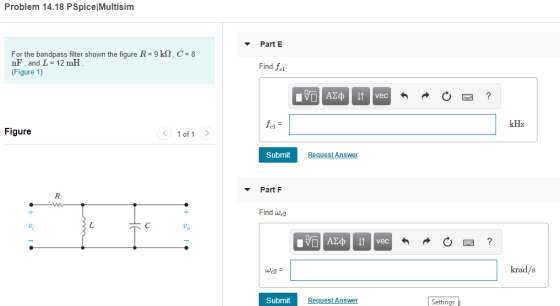
Problem 14.18 PSpice Multisim Part E k2, C 8 For the bandpass filter shown the figure R nF, and L 12 mHH (Figure 1) 9 Find fal vec kHz Figure 1 of 1 Submit Request Ans Part F Find we2 vec krad/s Submit Request Answer Settings
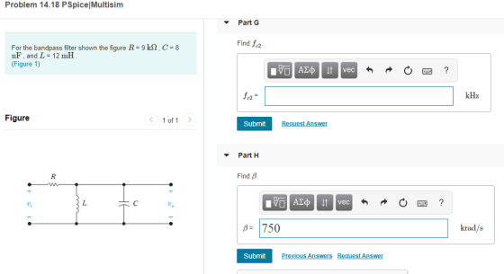
Problem 14.18 PSpice Multisim Part G Find 1c2 For the bandpass filter shown the figure R- 9 k2, C 8 nF, and L 12 mHH (Figure 1) vec kHz c2 Figure 1 of1 Submit Request Answen Part H Find B vec B 750 krad/s Submit ious Ans Request Answen
Homework Answers


Add Answer to:
Problem 14.18 PSpice Multisim Part C Find Q For the bandpass filter shown the fiqure R 9 kSn,C 8 ...
Homework #2 Problem 14.38 PSpice Multisim Part A Consider the bandreject filter shown in (Figure 1)....
 Homework #2 Problem 14.38 PSpice Multisim Part A Consider the bandreject filter shown in (Figure 1). Suppose that R-4 k2,L-3.5 mH, C-62.5 nF Calculate the center frequency wo. Express your answer using three significant figures vec krad/s Figure 1 of 1 Submit Request Answen Part B Calculate the center frequency f, in kilohertz. Express your answer using three significant figures vec kHz Problem 14.38 PSpice Multisim Part C Consider the bandreject filter shown in (Figure 1). Suppose that R-4 k2,L-3.5...
Scale the bandpass filter in (Figure 1) so that the center frequency is 180 kHz and...
 Scale the bandpass filter in (Figure 1) so that the center frequency is 180 kHz and the quality factor is 8, using a 2.5 nF capacitor. Figure < 1 of 1 > 8k 310 mH 10 nF Part A Determine the value of the resistor of the scaled filter Express your answer to three significant figures and include the appropriate units. R = Value Units Submit Request Answer Part B Determine the value of the inductor of the scaled filter...
Problem 4 Use a 5 nF capacitor to design a series RLC bandpass filter. The center...
 Problem 4 Use a 5 nF capacitor to design a series RLC bandpass filter. The center frequency the filter is 8 kHz, and the quality factor is 1.5. Part A Specify the value of L. View Available Hint(s) EVO AQH vec ? L = 0.079 ml Submit Previous Answers * Incorrect; Try Again; 8 attempts remaining Part B Specify the value of R. 10 AEDIf vec ? R = k12 Submit Request Answer Problem 4 Use a 5 nF capacitor...
PartA Design a series RLC bandpass filter using only three components from Appendix H that comes ...
 PartA Design a series RLC bandpass filter using only three components from Appendix H that comes closest to the filter with a quality factor of 2 and a center frequency of 8 kHz Choose L 10 mH. Then, what is the value of C? vec AF Submit Request Answen Part B What is the value of R? vec Problem 14.28 Part Design a series RLC bandpass filter using only three components from Appendix H that comes closest to the filter...
Consider the series RLC bandpass filter shown in (Figure 1). The filter has a quality of...
 Consider the series RLC bandpass filter shown in (Figure 1). The filter has a quality of 2 and a center frequency of 8 kHz. The input to the filter is vi (t) = 23 cos wt V. Suppose that C = 5 nF. Figure < 1 of 1 + VLC с L HE + + Vi R} R V. Part E Find the voltage drop across the series combination of the inductor and capacitor when w=10w, Suppose that vlc (t)...
<Chapter (9) HW - 2% Problem 9.24 PSpice Multisim Part A For the circuit shown in...
 Problem 9.24 PSpice Multisim Part A For the circuit shown in (Figure 1), find the frequency at which the impedance Zab is purely resistive. Suppose R = 400 22 L = 350 mH and C = 50 uF. Express your answer using three significant figures.Part B Find the value of Zab at the frequency of Part A. Express your answer to two significant figures and include the appropriate units.
Problem 4.95 PSpice Multisim Part A Use the principle of superposition to find the current io...
 Problem 4.95 PSpice Multisim Part A Use the principle of superposition to find the current io in the circuit(Figure 1)if ii = 3.6 A泊= 13 A , and U-61 V Express your answer with the appropriate units. iValue Units Submit Request Answer Provide Feedback Figure 1of1 1Ω 5Ω 2012 60Ω 3011
5) Consider the following second-order bandpass filter. As input voltage, apply V(t) 100Ω, C-4.7 μF. and L-10mH. sin(wt).R in Vout Fig 9: Second-order band-pass filter a) Determine the frequenc...
 5) Consider the following second-order bandpass filter. As input voltage, apply V(t) 100Ω, C-4.7 μF. and L-10mH. sin(wt).R in Vout Fig 9: Second-order band-pass filter a) Determine the frequency response function H(ju) Ve-ju) / Vm(ju) and sketch the magnitude and phase characteristics versus w by calaulation. Calculate the theoretical cutoff frequency of the filter Using PSpice AC analysis, plot magnitude lHju)l and phase ф characteristics of the filter, between 1 Hz-100 KHz b) c)
5) Consider the following second-order bandpass...
5) Consider the following second-order bandpass filter. As input voltage, apply V(t) 100Ω, C-4.7 μF. and L-10mH. sin(wt).R in Vout Fig 9: Second-order band-pass filter a) Determine the frequency response function H(ju) Ve-ju) / Vm(ju) and sketch the magnitude and phase characteristics versus w by calaulation. Calculate the theoretical cutoff frequency of the filter Using PSpice AC analysis, plot magnitude lHju)l and phase ф characteristics of the filter, between 1 Hz-100 KHz b) c)
5) Consider the following second-order bandpass...
Problem 5.24 Design Problem | PSpice|Multisim The circuit in the figure is a noninverting summing amplifier....
 Problem 5.24 Design Problem | PSpice|Multisim The circuit in the figure is a noninverting summing amplifier. Assume the op amp is ideal. Design the circuit so that v. = va + 2b + Suc (Figure 1) Part C Calculate ia when va=1.1 V, ub=0.2 V, and vc=1.2 V Express your answer with the appropriate units. Figure < 1 of 1 MA ? 100 k2 Value Units 20 KA2 .5 V Submit Previous Answers Request Answer + 1-5 V R 7.3...
Homework #5 Problem 4.67 PSpice Multisim 11 of 14> Find the Thevenin equivalent with respect to...
 Homework #5 Problem 4.67 PSpice Multisim 11 of 14> Find the Thevenin equivalent with respect to the terminals a,b for the circuit(Figure 1〕if u-690 V。 12 A PartA Find the equivalent voltage Express your answer with the appropriate units TValue Units Submit Request Answer Part B Figure 1 of 1 Find the equivalent resistance. Express your answer with the appropriate units. 30 0 RThValue Units 8Ω 5.2 Ω Submit Request Answer 12 2 Provide Feedback Next>
 Homework #2 Problem 14.38 PSpice Multisim Part A Consider the bandreject filter shown in (Figure 1). Suppose that R-4 k2,L-3.5 mH, C-62.5 nF Calculate the center frequency wo. Express your answer using three significant figures vec krad/s Figure 1 of 1 Submit Request Answen Part B Calculate the center frequency f, in kilohertz. Express your answer using three significant figures vec kHz Problem 14.38 PSpice Multisim Part C Consider the bandreject filter shown in (Figure 1). Suppose that R-4 k2,L-3.5...
 Scale the bandpass filter in (Figure 1) so that the center frequency is 180 kHz and the quality factor is 8, using a 2.5 nF capacitor. Figure < 1 of 1 > 8k 310 mH 10 nF Part A Determine the value of the resistor of the scaled filter Express your answer to three significant figures and include the appropriate units. R = Value Units Submit Request Answer Part B Determine the value of the inductor of the scaled filter...
 Problem 4 Use a 5 nF capacitor to design a series RLC bandpass filter. The center frequency the filter is 8 kHz, and the quality factor is 1.5. Part A Specify the value of L. View Available Hint(s) EVO AQH vec ? L = 0.079 ml Submit Previous Answers * Incorrect; Try Again; 8 attempts remaining Part B Specify the value of R. 10 AEDIf vec ? R = k12 Submit Request Answer Problem 4 Use a 5 nF capacitor...
 PartA Design a series RLC bandpass filter using only three components from Appendix H that comes closest to the filter with a quality factor of 2 and a center frequency of 8 kHz Choose L 10 mH. Then, what is the value of C? vec AF Submit Request Answen Part B What is the value of R? vec Problem 14.28 Part Design a series RLC bandpass filter using only three components from Appendix H that comes closest to the filter...
 Consider the series RLC bandpass filter shown in (Figure 1). The filter has a quality of 2 and a center frequency of 8 kHz. The input to the filter is vi (t) = 23 cos wt V. Suppose that C = 5 nF. Figure < 1 of 1 + VLC с L HE + + Vi R} R V. Part E Find the voltage drop across the series combination of the inductor and capacitor when w=10w, Suppose that vlc (t)...
 Problem 9.24 PSpice Multisim Part A For the circuit shown in (Figure 1), find the frequency at which the impedance Zab is purely resistive. Suppose R = 400 22 L = 350 mH and C = 50 uF. Express your answer using three significant figures.Part B Find the value of Zab at the frequency of Part A. Express your answer to two significant figures and include the appropriate units.
 Problem 4.95 PSpice Multisim Part A Use the principle of superposition to find the current io in the circuit(Figure 1)if ii = 3.6 A泊= 13 A , and U-61 V Express your answer with the appropriate units. iValue Units Submit Request Answer Provide Feedback Figure 1of1 1Ω 5Ω 2012 60Ω 3011
 5) Consider the following second-order bandpass filter. As input voltage, apply V(t) 100Ω, C-4.7 μF. and L-10mH. sin(wt).R in Vout Fig 9: Second-order band-pass filter a) Determine the frequency response function H(ju) Ve-ju) / Vm(ju) and sketch the magnitude and phase characteristics versus w by calaulation. Calculate the theoretical cutoff frequency of the filter Using PSpice AC analysis, plot magnitude lHju)l and phase ф characteristics of the filter, between 1 Hz-100 KHz b) c)
5) Consider the following second-order bandpass...
5) Consider the following second-order bandpass filter. As input voltage, apply V(t) 100Ω, C-4.7 μF. and L-10mH. sin(wt).R in Vout Fig 9: Second-order band-pass filter a) Determine the frequency response function H(ju) Ve-ju) / Vm(ju) and sketch the magnitude and phase characteristics versus w by calaulation. Calculate the theoretical cutoff frequency of the filter Using PSpice AC analysis, plot magnitude lHju)l and phase ф characteristics of the filter, between 1 Hz-100 KHz b) c)
5) Consider the following second-order bandpass...
 Problem 5.24 Design Problem | PSpice|Multisim The circuit in the figure is a noninverting summing amplifier. Assume the op amp is ideal. Design the circuit so that v. = va + 2b + Suc (Figure 1) Part C Calculate ia when va=1.1 V, ub=0.2 V, and vc=1.2 V Express your answer with the appropriate units. Figure < 1 of 1 MA ? 100 k2 Value Units 20 KA2 .5 V Submit Previous Answers Request Answer + 1-5 V R 7.3...
 Homework #5 Problem 4.67 PSpice Multisim 11 of 14> Find the Thevenin equivalent with respect to the terminals a,b for the circuit(Figure 1〕if u-690 V。 12 A PartA Find the equivalent voltage Express your answer with the appropriate units TValue Units Submit Request Answer Part B Figure 1 of 1 Find the equivalent resistance. Express your answer with the appropriate units. 30 0 RThValue Units 8Ω 5.2 Ω Submit Request Answer 12 2 Provide Feedback Next>
Most questions answered within 3 hours.
-
Where is the error in this code sequence?
String s1 = "Hello";
String s2 = "ello";...
asked 10 months ago -
Financial data for Joel de Paris, Inc., for last year
follow:
Joel de Paris, Inc.
Balance...
asked 10 months ago -
Consider this reaction:
Al2(SO4)3 (aq)+ BaCl3
(aq) Al2Cl6 (aq)- +
3BaSO4(s) . What is the...
asked 10 months ago -
Suppose that Savneet is considering increasing her
recent random sample from 20 car rentals to 40...
asked 10 months ago -
Trucks arrive at an unloading terminal at an average rate of 120
per hour.
Trucks arrive...
asked 10 months ago -
Why are methanol and ethanol completely soluble in water while
octanol is not very little soluble....
asked 10 months ago -
A facilities manager at a university reads in a research report
that the mean amount of...
asked 10 months ago -
When the CuSO4 is rehydrated by adding water to the anhydrous
compound, is this an endothermic...
asked 10 months ago -
A ray of sunlight is passing from diamond into crown glass; the
angle of incidence is...
asked 10 months ago -
A block of mass 0.249 kg is placed on top of a light, vertical
spring of...
asked 10 months ago -
how do the kidneys compensate in the presences of acidosis
a) trigger hyperventilate
b) reserve acid...
asked 10 months ago -
Question 501 pts
The rental rate of capital to the firm increases. Which of the
following...
asked 10 months ago