5. (4) Consider an RL circuit that can initially be thought of as containing an ideal...
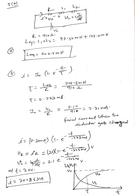
5. (4) Consider an RL circuit that can initially be thought of as containing an ideal battery of voltage 2.10 V, an ideal resistor of resistance 910 Ω and an ideal inductor of inductance 77.50 mH.
(a) Another ideal inductor, of inductance 125.0 mH, is added in series. Find the new equivalent inductance and the new time constant for the circuit.
(b) The circuit is closed at t=0. Sketch the behaviour of the voltage across the resistor and the voltage across the inductor as a function of time
(c) Find the current in the circuit at time t=3.00 μs.
Homework Answers
Add Answer to:
5. (4) Consider an RL circuit that can initially be thought of
as containing an ideal...
Magnetism 1. (4) An unknown particle travelling at a velocity of 2.20x10⁶ m/s to the right...
Magnetism 1. (4) An unknown particle travelling at a velocity of 2.20x10⁶ m/s to the right as seen by an observer, enters a region that has an electric field of magnitude 750 V/m pointed away from the observer. Ignore gravity for this question. (a) What is the direction and magnitude of the perpendicular magnetic field which would best cancel out the effect of the electric field so that the particle passes through undeflected? (b) If while travelling 0.200 m, with...
An RL circuit is assembled with a 24.0 V ideal battery connected by a switch to...
An RL circuit is assembled with a 24.0 V ideal battery connected by a switch to a 37.5 mH inductor and 50.0 Ω resistor. a) How long, in ms, after the switch is closed does the current in the resistor reach 63.2% of its final value? BLANK-1 b) What is the maximum current, in Amperes, coming out of the voltage source after a very long time? BLANK-2 c) What is the current, in Amperes, through the resistor, 0.95 ms after...
An RL circuit bas a 30 12 resistor in series with an 840 mH inductor and...
 An RL circuit bas a 30 12 resistor in series with an 840 mH inductor and a 12 V battery, as shown. The service is closed at t - 0.Find the time constant of the circuit What is the current in the circuit 0.014 s after the switch is eloped? What energy is stored in the inductance at this time (0.014 s after the switch is closed)?
1. An RL circuit comprised of one resistor and one inductor is shown in the figure...
 1. An RL circuit comprised of one resistor and one inductor is shown in the figure below. The resistor and inductor are connected to a source of emf with negligible internal resistance by a switch a. The emf for this circuit is 12.0 V. The resistance of the resistor is 0.35 12, and the inductance of the inductor is 53 mH. For the circuit below: a. Sketch the graph of current through the inductor as a function of time after...
The rms current in an RL circuit is 0.21 A when it is connected to an...
The rms current in an RL circuit is 0.21 A when it is connected to an ac generator with a frequency of 50 Hz and an rms voltage of 30 V . Part A Given that the inductor has an inductance of 170 mH , what is the resistance of the resistor? Part B Find the rms voltage across the resistor. Part C Find the rms voltage across the inductor.
An ideal inductor of inductance 7.7 mH is connected in parallel with a resistor of resistance...
An ideal inductor of inductance 7.7 mH is connected in parallel with a resistor of resistance 141 Ω. This parallel combination is then connected in series with a second ideal inductor of inductance 4.5 mH. The sinusoidal voltage source for the circuit is 102 V, 71.6 Hz. Sketch the circuit and find the magnitude of the current, I, flowing through the resistor.
1. An RL circuit comprised of one resistor and one inductor is shown in the figure below. The resistor and inductor...
 1. An RL circuit comprised of one resistor and one inductor is shown in the figure below. The resistor and inductor are connected to a source of emf with negligible internal resistance by a switch a. The emf for this circuit is 12.0 V. The resistance of the resistor is 0.35 , and the inductance of the inductor is 53 mH. For the circuit below: a. Sketch the graph of current through the inductor as a function of time after...
Help please ...! An RL circuit comprised of one resistor and one inductor is shown in...
 Help please ...!
An RL circuit comprised of one resistor and one inductor is shown in the figure below. The resistor and inductor are connected to a source of emf with negligible internal resistance by a switch a. The emf for this circuit is 12.0 V. The resistance of the resistor is 0.35 Q, and the inductance of the inductor is 53 mH. For the circuit below: Sketch the graph of current through the inductor as a function of time...
Help please ...!
An RL circuit comprised of one resistor and one inductor is shown in the figure below. The resistor and inductor are connected to a source of emf with negligible internal resistance by a switch a. The emf for this circuit is 12.0 V. The resistance of the resistor is 0.35 Q, and the inductance of the inductor is 53 mH. For the circuit below: Sketch the graph of current through the inductor as a function of time...
GOAL Calculate a time constant and relate it to current in an RL circuit. PROBLEM A...
 GOAL Calculate a time constant and relate it to
current in an RL circuit.
PROBLEM A 12.6-V battery is in a circuit with a
30.0-mH inductor and a 0.150-? resistor. The switch is closed at
t = 0. (a) Find the time constant of the
circuit. (b) Find the current after one time
constant has elapsed. (c) Find the voltage drops
across the resistor when t = 0 and t = one time
constant. (d) What's the rate of change...
GOAL Calculate a time constant and relate it to
current in an RL circuit.
PROBLEM A 12.6-V battery is in a circuit with a
30.0-mH inductor and a 0.150-? resistor. The switch is closed at
t = 0. (a) Find the time constant of the
circuit. (b) Find the current after one time
constant has elapsed. (c) Find the voltage drops
across the resistor when t = 0 and t = one time
constant. (d) What's the rate of change...
 An RL circuit bas a 30 12 resistor in series with an 840 mH inductor and a 12 V battery, as shown. The service is closed at t - 0.Find the time constant of the circuit What is the current in the circuit 0.014 s after the switch is eloped? What energy is stored in the inductance at this time (0.014 s after the switch is closed)?
 1. An RL circuit comprised of one resistor and one inductor is shown in the figure below. The resistor and inductor are connected to a source of emf with negligible internal resistance by a switch a. The emf for this circuit is 12.0 V. The resistance of the resistor is 0.35 12, and the inductance of the inductor is 53 mH. For the circuit below: a. Sketch the graph of current through the inductor as a function of time after...
 1. An RL circuit comprised of one resistor and one inductor is shown in the figure below. The resistor and inductor are connected to a source of emf with negligible internal resistance by a switch a. The emf for this circuit is 12.0 V. The resistance of the resistor is 0.35 12, and the inductance of the inductor is 53 mH. For the circuit below: a. Sketch the graph of current through the inductor as a function of time after...
 1. An RL circuit comprised of one resistor and one inductor is shown in the figure below. The resistor and inductor are connected to a source of emf with negligible internal resistance by a switch a. The emf for this circuit is 12.0 V. The resistance of the resistor is 0.35 , and the inductance of the inductor is 53 mH. For the circuit below: a. Sketch the graph of current through the inductor as a function of time after...
 Help please ...!
An RL circuit comprised of one resistor and one inductor is shown in the figure below. The resistor and inductor are connected to a source of emf with negligible internal resistance by a switch a. The emf for this circuit is 12.0 V. The resistance of the resistor is 0.35 Q, and the inductance of the inductor is 53 mH. For the circuit below: Sketch the graph of current through the inductor as a function of time...
Help please ...!
An RL circuit comprised of one resistor and one inductor is shown in the figure below. The resistor and inductor are connected to a source of emf with negligible internal resistance by a switch a. The emf for this circuit is 12.0 V. The resistance of the resistor is 0.35 Q, and the inductance of the inductor is 53 mH. For the circuit below: Sketch the graph of current through the inductor as a function of time...
 GOAL Calculate a time constant and relate it to
current in an RL circuit.
PROBLEM A 12.6-V battery is in a circuit with a
30.0-mH inductor and a 0.150-? resistor. The switch is closed at
t = 0. (a) Find the time constant of the
circuit. (b) Find the current after one time
constant has elapsed. (c) Find the voltage drops
across the resistor when t = 0 and t = one time
constant. (d) What's the rate of change...
GOAL Calculate a time constant and relate it to
current in an RL circuit.
PROBLEM A 12.6-V battery is in a circuit with a
30.0-mH inductor and a 0.150-? resistor. The switch is closed at
t = 0. (a) Find the time constant of the
circuit. (b) Find the current after one time
constant has elapsed. (c) Find the voltage drops
across the resistor when t = 0 and t = one time
constant. (d) What's the rate of change...
Most questions answered within 3 hours.
-
Where is the error in this code sequence?
String s1 = "Hello";
String s2 = "ello";...
asked 10 months ago -
Financial data for Joel de Paris, Inc., for last year
follow:
Joel de Paris, Inc.
Balance...
asked 10 months ago -
Consider this reaction:
Al2(SO4)3 (aq)+ BaCl3
(aq) Al2Cl6 (aq)- +
3BaSO4(s) . What is the...
asked 10 months ago -
Suppose that Savneet is considering increasing her
recent random sample from 20 car rentals to 40...
asked 10 months ago -
Trucks arrive at an unloading terminal at an average rate of 120
per hour.
Trucks arrive...
asked 10 months ago -
Why are methanol and ethanol completely soluble in water while
octanol is not very little soluble....
asked 10 months ago -
A facilities manager at a university reads in a research report
that the mean amount of...
asked 10 months ago -
When the CuSO4 is rehydrated by adding water to the anhydrous
compound, is this an endothermic...
asked 10 months ago -
A ray of sunlight is passing from diamond into crown glass; the
angle of incidence is...
asked 10 months ago -
A block of mass 0.249 kg is placed on top of a light, vertical
spring of...
asked 10 months ago -
how do the kidneys compensate in the presences of acidosis
a) trigger hyperventilate
b) reserve acid...
asked 10 months ago -
Question 501 pts
The rental rate of capital to the firm increases. Which of the
following...
asked 10 months ago