
Homework Answers
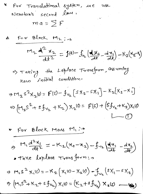
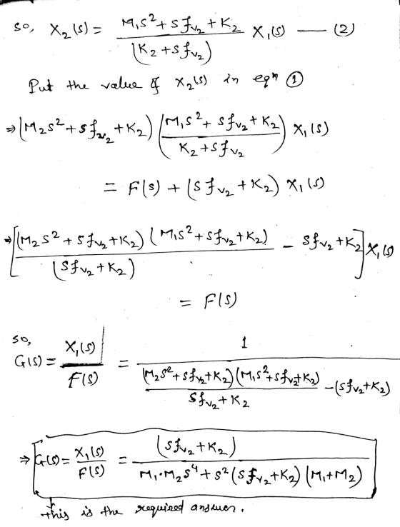
5. Consider the system below with m1 10 kg, m2-20 kg, b 20 N-s/m, k- 60...
 5. Consider the system below with m1 10 kg, m2-20 kg, b 20 N-s/m, k- 60 N/m and fas a step input of 10 N (a) Derive the transfer function of the system between fand z2. (b) Derive a state space representation of the system. (c) Use MATLAB to plot the output (z2 - z1) and (z2' - z1') m2
5. Find the transfer function X (3) F(s) and X:(5) F(s) for the mechanical system below...
 5. Find the transfer function X (3) F(s) and X:(5) F(s) for the mechanical system below Kj = 4 N/m *(1) K2 = 5 N/m 00002 0000 = 3 N-s/m M =1 kg|fv2 = 3 N-s/m M2 = 2 kg Svz = 2 N-s/m E
Mi k2 b yi m2 Figure 5-45 Mechanical system. Assuming that mi 10 kg, m2 5 kg, b 10 N-s/m, k 40 N/...
 mi k2 b yi m2 Figure 5-45 Mechanical system. Assuming that mi 10 kg, m2 5 kg, b 10 N-s/m, k 40 N/m, and k 20 N/m and that input force u is a constant force of 5 N, obtain the response of the sys- tem. Plot the response curves n(t) versus r and y2(t) versus t with MATLAB Problem B-5-23 Consider the system shown in Figure 5-45. The system is at rest for t < 0. The dis placements...
If possible can you show step by step because I'm new in this subject X1(S) X2(S)...
 If possible can you show step
by step because I'm new in this subject
X1(S) X2(S) Find the transfer function and for the mechanical system below F(S) F(S) K1 = 4 N/m X;(1) K2= 5 N/m -X2(1) 0000 0000 fv1 = 3 N-s/m M1 =1 kg|v2 = 3 N-s/m M2 = 2 kg Sva= 2 N-s/m HE
If possible can you show step
by step because I'm new in this subject
X1(S) X2(S) Find the transfer function and for the mechanical system below F(S) F(S) K1 = 4 N/m X;(1) K2= 5 N/m -X2(1) 0000 0000 fv1 = 3 N-s/m M1 =1 kg|v2 = 3 N-s/m M2 = 2 kg Sva= 2 N-s/m HE
Question 1-4 is about the following mechanical system: Data: ki-20 [N/m] b-2 [Ns/m] k2# 10 [N/m] m2 At) mi Question 1 X...
 Question 1-4 is about the following mechanical system: Data: ki-20 [N/m] b-2 [Ns/m] k2# 10 [N/m] m2 At) mi Question 1 X1(s) Develop the symbolic transfer function G1(s)2 F(s) 1.1 Determine the differential equation, that this transfer function describe 1.2 Question 2 Sketch the step response for G1(s), using Matlab and explain the process 2.1 Sketch the pole /zero diagram for the transfer function G1(s) and reflect on the relation between the step response and the pole /zero diagram 2.2...
For a mass-spring-damper mechanical systems shown below, x200) K1-1 N/m 0000 -X,(0) K-1 N/m 00004 =...
 For a mass-spring-damper mechanical systems shown below, x200) K1-1 N/m 0000 -X,(0) K-1 N/m 00004 = 1 N-s/m fr2 M1=1 kg = 2 N-s/m M2 -1 kg 13 = 1 N-s/m 1. Find the differential equations relating input force f(t) and output displacement xi(t) and x2(C) in the system. (40 marks) (Hint: K, fy and M are spring constant, friction coefficient and mass respectively) 2. Determine the transfer function G(s)= X1(s)/F(s) (20 marks)
Can you show step by step calculation. Thank you Find the transfer function X (5) F(s)...
 Can you show step by step calculation. Thank
you
Find the transfer function X (5) F(s) and X2() for the mechanical system below F(8) X (1) Ki = 4 N/m K2 = 5 N/m 0000 0000 tvi = 3 N-s/m My = 1 kg fv2 = 3 N-s/m fin 2 N-s/m M2 = 2 kg fv3 =
Can you show step by step calculation. Thank
you
Find the transfer function X (5) F(s) and X2() for the mechanical system below F(8) X (1) Ki = 4 N/m K2 = 5 N/m 0000 0000 tvi = 3 N-s/m My = 1 kg fv2 = 3 N-s/m fin 2 N-s/m M2 = 2 kg fv3 =
26. For the system of Figure P2.12 find the transfer function, G(s)X1(s)/F(s). [Section: 2.5] Xi(1)K2 =...
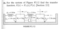 26. For the system of Figure P2.12 find the transfer function, G(s)X1(s)/F(s). [Section: 2.5] Xi(1)K2 = 5 N/m 2(0) fr) FIGURE P2.12
MEMB343 MECHANICAL VIBRATIONS ASSIGNMENT l. For the system shown in Figure 1, where mi=5 kg, m,-10 kg, ki=1000 N/m, k2-500 N/m, k, 2000 N/m, fi-100sin(15t) N and f-0, use modal analysis to determine...
 MEMB343 MECHANICAL VIBRATIONS ASSIGNMENT l. For the system shown in Figure 1, where mi=5 kg, m,-10 kg, ki=1000 N/m, k2-500 N/m, k, 2000 N/m, fi-100sin(15t) N and f-0, use modal analysis to determine the amplitudes of masses m, and m2. The equations of motion are given as sin(15t), wth natura frequencies 5 01[i, 0 10 500-500x, 500 2500jx, x,[100 ω,-14.14 rad's and a, = 18.71 rad/s, and mode shapes, Φ',, and Φ' k, Im Figure 1
MEMB343 MECHANICAL VIBRATIONS ASSIGNMENT...
MEMB343 MECHANICAL VIBRATIONS ASSIGNMENT l. For the system shown in Figure 1, where mi=5 kg, m,-10 kg, ki=1000 N/m, k2-500 N/m, k, 2000 N/m, fi-100sin(15t) N and f-0, use modal analysis to determine the amplitudes of masses m, and m2. The equations of motion are given as sin(15t), wth natura frequencies 5 01[i, 0 10 500-500x, 500 2500jx, x,[100 ω,-14.14 rad's and a, = 18.71 rad/s, and mode shapes, Φ',, and Φ' k, Im Figure 1
MEMB343 MECHANICAL VIBRATIONS ASSIGNMENT...
Find the transfer function, X1(s)/F(s) for the diagram below A consultant engineer is assigned by his...
 Find the transfer function, X1(s)/F(s) for the diagram
below
A consultant engineer is assigned by his manager to obtain the transfer function X1 F(s) for train carriage model as shown in Figure below. Given that K1 -5 N/m, K2 = 7 N/m, fv1 = 4 N-s/m.fv2 = 3 N-s/m.fv3 = 2 N-5/m and M1-M2 = 1kg. X1 (t) Xz(t) fv1 M fit Frictionless
Find the transfer function, X1(s)/F(s) for the diagram
below
A consultant engineer is assigned by his manager to obtain the transfer function X1 F(s) for train carriage model as shown in Figure below. Given that K1 -5 N/m, K2 = 7 N/m, fv1 = 4 N-s/m.fv2 = 3 N-s/m.fv3 = 2 N-5/m and M1-M2 = 1kg. X1 (t) Xz(t) fv1 M fit Frictionless
 5. Consider the system below with m1 10 kg, m2-20 kg, b 20 N-s/m, k- 60 N/m and fas a step input of 10 N (a) Derive the transfer function of the system between fand z2. (b) Derive a state space representation of the system. (c) Use MATLAB to plot the output (z2 - z1) and (z2' - z1') m2
 5. Find the transfer function X (3) F(s) and X:(5) F(s) for the mechanical system below Kj = 4 N/m *(1) K2 = 5 N/m 00002 0000 = 3 N-s/m M =1 kg|fv2 = 3 N-s/m M2 = 2 kg Svz = 2 N-s/m E
 mi k2 b yi m2 Figure 5-45 Mechanical system. Assuming that mi 10 kg, m2 5 kg, b 10 N-s/m, k 40 N/m, and k 20 N/m and that input force u is a constant force of 5 N, obtain the response of the sys- tem. Plot the response curves n(t) versus r and y2(t) versus t with MATLAB Problem B-5-23 Consider the system shown in Figure 5-45. The system is at rest for t < 0. The dis placements...
 If possible can you show step
by step because I'm new in this subject
X1(S) X2(S) Find the transfer function and for the mechanical system below F(S) F(S) K1 = 4 N/m X;(1) K2= 5 N/m -X2(1) 0000 0000 fv1 = 3 N-s/m M1 =1 kg|v2 = 3 N-s/m M2 = 2 kg Sva= 2 N-s/m HE
If possible can you show step
by step because I'm new in this subject
X1(S) X2(S) Find the transfer function and for the mechanical system below F(S) F(S) K1 = 4 N/m X;(1) K2= 5 N/m -X2(1) 0000 0000 fv1 = 3 N-s/m M1 =1 kg|v2 = 3 N-s/m M2 = 2 kg Sva= 2 N-s/m HE
 Question 1-4 is about the following mechanical system: Data: ki-20 [N/m] b-2 [Ns/m] k2# 10 [N/m] m2 At) mi Question 1 X1(s) Develop the symbolic transfer function G1(s)2 F(s) 1.1 Determine the differential equation, that this transfer function describe 1.2 Question 2 Sketch the step response for G1(s), using Matlab and explain the process 2.1 Sketch the pole /zero diagram for the transfer function G1(s) and reflect on the relation between the step response and the pole /zero diagram 2.2...
 For a mass-spring-damper mechanical systems shown below, x200) K1-1 N/m 0000 -X,(0) K-1 N/m 00004 = 1 N-s/m fr2 M1=1 kg = 2 N-s/m M2 -1 kg 13 = 1 N-s/m 1. Find the differential equations relating input force f(t) and output displacement xi(t) and x2(C) in the system. (40 marks) (Hint: K, fy and M are spring constant, friction coefficient and mass respectively) 2. Determine the transfer function G(s)= X1(s)/F(s) (20 marks)
 Can you show step by step calculation. Thank
you
Find the transfer function X (5) F(s) and X2() for the mechanical system below F(8) X (1) Ki = 4 N/m K2 = 5 N/m 0000 0000 tvi = 3 N-s/m My = 1 kg fv2 = 3 N-s/m fin 2 N-s/m M2 = 2 kg fv3 =
Can you show step by step calculation. Thank
you
Find the transfer function X (5) F(s) and X2() for the mechanical system below F(8) X (1) Ki = 4 N/m K2 = 5 N/m 0000 0000 tvi = 3 N-s/m My = 1 kg fv2 = 3 N-s/m fin 2 N-s/m M2 = 2 kg fv3 =
 26. For the system of Figure P2.12 find the transfer function, G(s)X1(s)/F(s). [Section: 2.5] Xi(1)K2 = 5 N/m 2(0) fr) FIGURE P2.12
 MEMB343 MECHANICAL VIBRATIONS ASSIGNMENT l. For the system shown in Figure 1, where mi=5 kg, m,-10 kg, ki=1000 N/m, k2-500 N/m, k, 2000 N/m, fi-100sin(15t) N and f-0, use modal analysis to determine the amplitudes of masses m, and m2. The equations of motion are given as sin(15t), wth natura frequencies 5 01[i, 0 10 500-500x, 500 2500jx, x,[100 ω,-14.14 rad's and a, = 18.71 rad/s, and mode shapes, Φ',, and Φ' k, Im Figure 1
MEMB343 MECHANICAL VIBRATIONS ASSIGNMENT...
MEMB343 MECHANICAL VIBRATIONS ASSIGNMENT l. For the system shown in Figure 1, where mi=5 kg, m,-10 kg, ki=1000 N/m, k2-500 N/m, k, 2000 N/m, fi-100sin(15t) N and f-0, use modal analysis to determine the amplitudes of masses m, and m2. The equations of motion are given as sin(15t), wth natura frequencies 5 01[i, 0 10 500-500x, 500 2500jx, x,[100 ω,-14.14 rad's and a, = 18.71 rad/s, and mode shapes, Φ',, and Φ' k, Im Figure 1
MEMB343 MECHANICAL VIBRATIONS ASSIGNMENT...
 Find the transfer function, X1(s)/F(s) for the diagram
below
A consultant engineer is assigned by his manager to obtain the transfer function X1 F(s) for train carriage model as shown in Figure below. Given that K1 -5 N/m, K2 = 7 N/m, fv1 = 4 N-s/m.fv2 = 3 N-s/m.fv3 = 2 N-5/m and M1-M2 = 1kg. X1 (t) Xz(t) fv1 M fit Frictionless
Find the transfer function, X1(s)/F(s) for the diagram
below
A consultant engineer is assigned by his manager to obtain the transfer function X1 F(s) for train carriage model as shown in Figure below. Given that K1 -5 N/m, K2 = 7 N/m, fv1 = 4 N-s/m.fv2 = 3 N-s/m.fv3 = 2 N-5/m and M1-M2 = 1kg. X1 (t) Xz(t) fv1 M fit Frictionless
Most questions answered within 3 hours.
-
Where is the error in this code sequence?
String s1 = "Hello";
String s2 = "ello";...
asked 11 months ago -
Financial data for Joel de Paris, Inc., for last year
follow:
Joel de Paris, Inc.
Balance...
asked 11 months ago -
Consider this reaction:
Al2(SO4)3 (aq)+ BaCl3
(aq) Al2Cl6 (aq)- +
3BaSO4(s) . What is the...
asked 11 months ago -
Suppose that Savneet is considering increasing her
recent random sample from 20 car rentals to 40...
asked 11 months ago -
Trucks arrive at an unloading terminal at an average rate of 120
per hour.
Trucks arrive...
asked 11 months ago -
Why are methanol and ethanol completely soluble in water while
octanol is not very little soluble....
asked 11 months ago -
A facilities manager at a university reads in a research report
that the mean amount of...
asked 11 months ago -
When the CuSO4 is rehydrated by adding water to the anhydrous
compound, is this an endothermic...
asked 11 months ago -
A ray of sunlight is passing from diamond into crown glass; the
angle of incidence is...
asked 11 months ago -
A block of mass 0.249 kg is placed on top of a light, vertical
spring of...
asked 11 months ago -
how do the kidneys compensate in the presences of acidosis
a) trigger hyperventilate
b) reserve acid...
asked 11 months ago -
Question 501 pts
The rental rate of capital to the firm increases. Which of the
following...
asked 11 months ago