


![LR v3sc =-vlsC+02 C+v2 #+250] (5.11) Equations (5.9. (5.10) and (5.11) may be solved hy elimination and back substitution giv](http://img.homeworklib.com/questions/d7eb6a10-e8e1-11ea-9413-87d837e56500.png?x-oss-process=image/resize,w_560)

Homework Answers
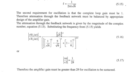
The given circuit are oscillator.
Important points in oscillator by making postive feedback or phase shift 180 degree even without input ac there will be sustained oscillation in the circuit.
Doubt may come with out input how can oscillator produce output waveform actually it takes energy from DC signal given fir biasing and uses it to produce output.
General procedure to solve is to may the phase shift in feedback path as 180 degree.
And then solve by using network analysis and put imaginary part =o to get relation for frequency since at 180 degree phase shift imaginary part is zero.
The frequency is derived in above problem using this criteria only.
Add Answer to:
Vout should be a sinusoid signal of 12Vp-p
Dc voltage to uA741 : +/-8.5V
Please simulate...
(a) Design a inverting Schmitt trigger circuit to be used as a zero crossing detector with transition voltages about ±25...
 (a) Design a inverting Schmitt trigger circuit
to be used as a zero crossing detector with transition voltages
about ±25 mV. Assume the saturation voltages for the op–amp are ±13
V. Draw the voltage transfer characteristic (VTC), i.e., vout vs.
vin.
(b) Design an astable multivibrator to produce
a square signal with a frequency of 1 kHz using C=0.01 µF, R1 = 30
kΩ, and R2 = 20 kΩ. Sketch the circuit waveforms (vo, v +, and v −)
assuming...
(a) Design a inverting Schmitt trigger circuit
to be used as a zero crossing detector with transition voltages
about ±25 mV. Assume the saturation voltages for the op–amp are ±13
V. Draw the voltage transfer characteristic (VTC), i.e., vout vs.
vin.
(b) Design an astable multivibrator to produce
a square signal with a frequency of 1 kHz using C=0.01 µF, R1 = 30
kΩ, and R2 = 20 kΩ. Sketch the circuit waveforms (vo, v +, and v −)
assuming...
Problem 1130 pts 1. [12 pts] For the circuit shown in Fig. 1, istance Rm when the switch is open. What type of voltage gain Vo/Vin and the input resistance Rin when the switch is close. What type of...
 Problem 1130 pts 1. [12 pts] For the circuit shown in Fig. 1, istance Rm when the switch is open. What type of voltage gain Vo/Vin and the input resistance Rin when the switch is close. What type of a) Find the voltage gain val vin and the input resistance Rin when the switch is open b) Find the amplifier is this? amplifier is this? tin vo R Fig. 1 [18 pts] Design a circuit that implements the following: Vo(t)...
3- OPERATIONAL-AMPLIFIER Nominating ampliar Voltage Show OW Difference ampliar Wate Date amplizier Close R Vout Voutin...
 3- OPERATIONAL-AMPLIFIER Nominating ampliar Voltage Show OW Difference ampliar Wate Date amplizier Close R Vout Voutin Vout = vin Buffer = Inverting amplifier Dout = (1 + .. Vout V out 1 V2 ERR Vour (, - v3) Differential Amplifier Non-Inverting amplifier 1- Refer to the op amp in Fig. If v; = 0.5 V, calculate: (a) the output voltage Vos (b) the current in the 10-k! resistor. 25k92 10k02 Oo + 6 2. A 741 op amp has an...
1. Find the transfer function Voda)/Vin(a) for the circuit shown in Figure 1 of the lab (where co...
 Please answer number 1
1. Find the transfer function Voda)/Vin(a) for the circuit shown in Figure 1 of the lab (where complex frequency variable s jo can be substituted for ease of analysis.) Calculate values for R and C such that the phase shift between the output and input is zero for an input frequency of 10kHz. What is the amplitude ratio (gain) of the output to the input at this frequency. 2. The RC network in figure 3 of...
Please answer number 1
1. Find the transfer function Voda)/Vin(a) for the circuit shown in Figure 1 of the lab (where complex frequency variable s jo can be substituted for ease of analysis.) Calculate values for R and C such that the phase shift between the output and input is zero for an input frequency of 10kHz. What is the amplitude ratio (gain) of the output to the input at this frequency. 2. The RC network in figure 3 of...
Please solve all parts pf the questions. Please show clear and neat work. Thank you! FEEDBACK AMPLIFIER ANALYSIS β,s/ Sa) Identify the feedback topology being used. Draw the B-network and You must j...
 Please solve all parts pf the questions. Please show clear and
neat work. Thank you!
FEEDBACK AMPLIFIER ANALYSIS β,s/ Sa) Identify the feedback topology being used. Draw the B-network and You must justify or explain find the numerical value for B- your answer for full credit (20 pts) 2 Assume matching transistors with DC bias voltage (or an ac ground) Sb) Draw and fully label the A-circuit (includes loading effects, R & R but NO feedback) p) Sc) Calculate the...
Please solve all parts pf the questions. Please show clear and
neat work. Thank you!
FEEDBACK AMPLIFIER ANALYSIS β,s/ Sa) Identify the feedback topology being used. Draw the B-network and You must justify or explain find the numerical value for B- your answer for full credit (20 pts) 2 Assume matching transistors with DC bias voltage (or an ac ground) Sb) Draw and fully label the A-circuit (includes loading effects, R & R but NO feedback) p) Sc) Calculate the...
ECE 202- Experiment 3-PreLab Homework NTROD TION TOTHE INTEG IRO T OP AMP VOLTAGE COMPARATOR 1....
 ECE 202- Experiment 3-PreLab Homework NTROD TION TOTHE INTEG IRO T OP AMP VOLTAGE COMPARATOR 1. Op Amp functions in two different modes, depending on the way it is connected in the circuit a) If there is no return loop, t is used to compare values of two input terminals (or as Explain how vo changes depending on the values of vi and v Vo . what are max and/or min values for v and vo? 2·The circuit shown below...
Yes, this is one problem. Please solve ALL PARTS. Guaranteed thumbs up for the person who solves it. 3 1. Photodiode...
 Yes, this is one problem. Please solve ALL PARTS. Guaranteed
thumbs up for the person who solves it.
3 1. Photodiode amplifier circuit You are designinga CF photosensor circuit for a light detection and ranging LiDAR) system in autonomous vehicles. The circuit utilizes a transimpedance amplifier to convert low-level RF photodiode current signal to a usable voltage output. It consists of a photodiode, an amplifier, and feedback capacitor/resistor pair as shown in Figure 1. We will derive simple equations to...
Yes, this is one problem. Please solve ALL PARTS. Guaranteed
thumbs up for the person who solves it.
3 1. Photodiode amplifier circuit You are designinga CF photosensor circuit for a light detection and ranging LiDAR) system in autonomous vehicles. The circuit utilizes a transimpedance amplifier to convert low-level RF photodiode current signal to a usable voltage output. It consists of a photodiode, an amplifier, and feedback capacitor/resistor pair as shown in Figure 1. We will derive simple equations to...
please make sure you are correct 1. Select configuration for a single-transistor amplifier with a gain...
 please make sure you are correct
1. Select configuration for a single-transistor amplifier with a gain of 30 dB and input resistance of 5 Mohm. A) common-emitter; b) common-gate; c) common-source; d)common-collector; e) cannot be implemented by single stage amplifier. 2. Select configuration for a single-transistor amplifier with a gain close to 0 dB and input resistance of 5 Mohm and load resistor of 50 ohm. a) common-emitter; b) common-gate; c) common-source; d)common-collector; e) cannot be implemented by single stage...
please make sure you are correct
1. Select configuration for a single-transistor amplifier with a gain of 30 dB and input resistance of 5 Mohm. A) common-emitter; b) common-gate; c) common-source; d)common-collector; e) cannot be implemented by single stage amplifier. 2. Select configuration for a single-transistor amplifier with a gain close to 0 dB and input resistance of 5 Mohm and load resistor of 50 ohm. a) common-emitter; b) common-gate; c) common-source; d)common-collector; e) cannot be implemented by single stage...
please answer all spring 2019 Name 19. Gain Margin (dB) is: e1OdByb) 15dBa c) 20 d8;...
 please answer all
spring 2019 Name 19. Gain Margin (dB) is: e1OdByb) 15dBa c) 20 d8; d) 35dB; e) 45d8 20. Phase margin (degree) is close to: a) 0; b) 45pe90) 135) e) 180 21. A MOSFET transistor gm 2m5, Cgs 2pF, Ced 0.5pF, its cut-off frequency, ft, is close to: a) 100 b) 300MHz ) 60OMH)1GHe) SGH 22. The cut-off frequency of a BIT with gm-40m5, r pi-2.5Kohm, r o-20Kohm, c mu 1pF and c pi is close to:...
please answer all
spring 2019 Name 19. Gain Margin (dB) is: e1OdByb) 15dBa c) 20 d8; d) 35dB; e) 45d8 20. Phase margin (degree) is close to: a) 0; b) 45pe90) 135) e) 180 21. A MOSFET transistor gm 2m5, Cgs 2pF, Ced 0.5pF, its cut-off frequency, ft, is close to: a) 100 b) 300MHz ) 60OMH)1GHe) SGH 22. The cut-off frequency of a BIT with gm-40m5, r pi-2.5Kohm, r o-20Kohm, c mu 1pF and c pi is close to:...
CIRCUIT ANALYSIS! Electrical engineering! Knowledge of MATLAB required!!!! Professionals only! Please be clear and concise. MUST...
 CIRCUIT ANALYSIS!
Electrical engineering!
Knowledge of MATLAB required!!!!
Professionals only!
Please be clear and concise.
MUST ANSWER ALL PARTS OF QUESTION!!!!!!!! Credit only awarded to
all complete answers
Please circle answers
Use Loop Analysis to complete the elements of the Amatrix of the equation A*I=S, where A is the nodal matrix, I is the loop currents vector and Sis the sources vector for the circuit below: 13 Z1 212 2/0° 12%ºv + Is Vs 22 T 122 11 Z3j42 24...
CIRCUIT ANALYSIS!
Electrical engineering!
Knowledge of MATLAB required!!!!
Professionals only!
Please be clear and concise.
MUST ANSWER ALL PARTS OF QUESTION!!!!!!!! Credit only awarded to
all complete answers
Please circle answers
Use Loop Analysis to complete the elements of the Amatrix of the equation A*I=S, where A is the nodal matrix, I is the loop currents vector and Sis the sources vector for the circuit below: 13 Z1 212 2/0° 12%ºv + Is Vs 22 T 122 11 Z3j42 24...
 (a) Design a inverting Schmitt trigger circuit
to be used as a zero crossing detector with transition voltages
about ±25 mV. Assume the saturation voltages for the op–amp are ±13
V. Draw the voltage transfer characteristic (VTC), i.e., vout vs.
vin.
(b) Design an astable multivibrator to produce
a square signal with a frequency of 1 kHz using C=0.01 µF, R1 = 30
kΩ, and R2 = 20 kΩ. Sketch the circuit waveforms (vo, v +, and v −)
assuming...
(a) Design a inverting Schmitt trigger circuit
to be used as a zero crossing detector with transition voltages
about ±25 mV. Assume the saturation voltages for the op–amp are ±13
V. Draw the voltage transfer characteristic (VTC), i.e., vout vs.
vin.
(b) Design an astable multivibrator to produce
a square signal with a frequency of 1 kHz using C=0.01 µF, R1 = 30
kΩ, and R2 = 20 kΩ. Sketch the circuit waveforms (vo, v +, and v −)
assuming...
 Problem 1130 pts 1. [12 pts] For the circuit shown in Fig. 1, istance Rm when the switch is open. What type of voltage gain Vo/Vin and the input resistance Rin when the switch is close. What type of a) Find the voltage gain val vin and the input resistance Rin when the switch is open b) Find the amplifier is this? amplifier is this? tin vo R Fig. 1 [18 pts] Design a circuit that implements the following: Vo(t)...
 3- OPERATIONAL-AMPLIFIER Nominating ampliar Voltage Show OW Difference ampliar Wate Date amplizier Close R Vout Voutin Vout = vin Buffer = Inverting amplifier Dout = (1 + .. Vout V out 1 V2 ERR Vour (, - v3) Differential Amplifier Non-Inverting amplifier 1- Refer to the op amp in Fig. If v; = 0.5 V, calculate: (a) the output voltage Vos (b) the current in the 10-k! resistor. 25k92 10k02 Oo + 6 2. A 741 op amp has an...
 Please answer number 1
1. Find the transfer function Voda)/Vin(a) for the circuit shown in Figure 1 of the lab (where complex frequency variable s jo can be substituted for ease of analysis.) Calculate values for R and C such that the phase shift between the output and input is zero for an input frequency of 10kHz. What is the amplitude ratio (gain) of the output to the input at this frequency. 2. The RC network in figure 3 of...
Please answer number 1
1. Find the transfer function Voda)/Vin(a) for the circuit shown in Figure 1 of the lab (where complex frequency variable s jo can be substituted for ease of analysis.) Calculate values for R and C such that the phase shift between the output and input is zero for an input frequency of 10kHz. What is the amplitude ratio (gain) of the output to the input at this frequency. 2. The RC network in figure 3 of...
 Please solve all parts pf the questions. Please show clear and
neat work. Thank you!
FEEDBACK AMPLIFIER ANALYSIS β,s/ Sa) Identify the feedback topology being used. Draw the B-network and You must justify or explain find the numerical value for B- your answer for full credit (20 pts) 2 Assume matching transistors with DC bias voltage (or an ac ground) Sb) Draw and fully label the A-circuit (includes loading effects, R & R but NO feedback) p) Sc) Calculate the...
Please solve all parts pf the questions. Please show clear and
neat work. Thank you!
FEEDBACK AMPLIFIER ANALYSIS β,s/ Sa) Identify the feedback topology being used. Draw the B-network and You must justify or explain find the numerical value for B- your answer for full credit (20 pts) 2 Assume matching transistors with DC bias voltage (or an ac ground) Sb) Draw and fully label the A-circuit (includes loading effects, R & R but NO feedback) p) Sc) Calculate the...
 ECE 202- Experiment 3-PreLab Homework NTROD TION TOTHE INTEG IRO T OP AMP VOLTAGE COMPARATOR 1. Op Amp functions in two different modes, depending on the way it is connected in the circuit a) If there is no return loop, t is used to compare values of two input terminals (or as Explain how vo changes depending on the values of vi and v Vo . what are max and/or min values for v and vo? 2·The circuit shown below...
 Yes, this is one problem. Please solve ALL PARTS. Guaranteed
thumbs up for the person who solves it.
3 1. Photodiode amplifier circuit You are designinga CF photosensor circuit for a light detection and ranging LiDAR) system in autonomous vehicles. The circuit utilizes a transimpedance amplifier to convert low-level RF photodiode current signal to a usable voltage output. It consists of a photodiode, an amplifier, and feedback capacitor/resistor pair as shown in Figure 1. We will derive simple equations to...
Yes, this is one problem. Please solve ALL PARTS. Guaranteed
thumbs up for the person who solves it.
3 1. Photodiode amplifier circuit You are designinga CF photosensor circuit for a light detection and ranging LiDAR) system in autonomous vehicles. The circuit utilizes a transimpedance amplifier to convert low-level RF photodiode current signal to a usable voltage output. It consists of a photodiode, an amplifier, and feedback capacitor/resistor pair as shown in Figure 1. We will derive simple equations to...
 please make sure you are correct
1. Select configuration for a single-transistor amplifier with a gain of 30 dB and input resistance of 5 Mohm. A) common-emitter; b) common-gate; c) common-source; d)common-collector; e) cannot be implemented by single stage amplifier. 2. Select configuration for a single-transistor amplifier with a gain close to 0 dB and input resistance of 5 Mohm and load resistor of 50 ohm. a) common-emitter; b) common-gate; c) common-source; d)common-collector; e) cannot be implemented by single stage...
please make sure you are correct
1. Select configuration for a single-transistor amplifier with a gain of 30 dB and input resistance of 5 Mohm. A) common-emitter; b) common-gate; c) common-source; d)common-collector; e) cannot be implemented by single stage amplifier. 2. Select configuration for a single-transistor amplifier with a gain close to 0 dB and input resistance of 5 Mohm and load resistor of 50 ohm. a) common-emitter; b) common-gate; c) common-source; d)common-collector; e) cannot be implemented by single stage...
 please answer all
spring 2019 Name 19. Gain Margin (dB) is: e1OdByb) 15dBa c) 20 d8; d) 35dB; e) 45d8 20. Phase margin (degree) is close to: a) 0; b) 45pe90) 135) e) 180 21. A MOSFET transistor gm 2m5, Cgs 2pF, Ced 0.5pF, its cut-off frequency, ft, is close to: a) 100 b) 300MHz ) 60OMH)1GHe) SGH 22. The cut-off frequency of a BIT with gm-40m5, r pi-2.5Kohm, r o-20Kohm, c mu 1pF and c pi is close to:...
please answer all
spring 2019 Name 19. Gain Margin (dB) is: e1OdByb) 15dBa c) 20 d8; d) 35dB; e) 45d8 20. Phase margin (degree) is close to: a) 0; b) 45pe90) 135) e) 180 21. A MOSFET transistor gm 2m5, Cgs 2pF, Ced 0.5pF, its cut-off frequency, ft, is close to: a) 100 b) 300MHz ) 60OMH)1GHe) SGH 22. The cut-off frequency of a BIT with gm-40m5, r pi-2.5Kohm, r o-20Kohm, c mu 1pF and c pi is close to:...
 CIRCUIT ANALYSIS!
Electrical engineering!
Knowledge of MATLAB required!!!!
Professionals only!
Please be clear and concise.
MUST ANSWER ALL PARTS OF QUESTION!!!!!!!! Credit only awarded to
all complete answers
Please circle answers
Use Loop Analysis to complete the elements of the Amatrix of the equation A*I=S, where A is the nodal matrix, I is the loop currents vector and Sis the sources vector for the circuit below: 13 Z1 212 2/0° 12%ºv + Is Vs 22 T 122 11 Z3j42 24...
CIRCUIT ANALYSIS!
Electrical engineering!
Knowledge of MATLAB required!!!!
Professionals only!
Please be clear and concise.
MUST ANSWER ALL PARTS OF QUESTION!!!!!!!! Credit only awarded to
all complete answers
Please circle answers
Use Loop Analysis to complete the elements of the Amatrix of the equation A*I=S, where A is the nodal matrix, I is the loop currents vector and Sis the sources vector for the circuit below: 13 Z1 212 2/0° 12%ºv + Is Vs 22 T 122 11 Z3j42 24...
Most questions answered within 3 hours.
-
Where is the error in this code sequence?
String s1 = "Hello";
String s2 = "ello";...
asked 11 months ago -
Financial data for Joel de Paris, Inc., for last year
follow:
Joel de Paris, Inc.
Balance...
asked 11 months ago -
Consider this reaction:
Al2(SO4)3 (aq)+ BaCl3
(aq) Al2Cl6 (aq)- +
3BaSO4(s) . What is the...
asked 11 months ago -
Suppose that Savneet is considering increasing her
recent random sample from 20 car rentals to 40...
asked 11 months ago -
Trucks arrive at an unloading terminal at an average rate of 120
per hour.
Trucks arrive...
asked 11 months ago -
Why are methanol and ethanol completely soluble in water while
octanol is not very little soluble....
asked 11 months ago -
A facilities manager at a university reads in a research report
that the mean amount of...
asked 11 months ago -
When the CuSO4 is rehydrated by adding water to the anhydrous
compound, is this an endothermic...
asked 11 months ago -
A ray of sunlight is passing from diamond into crown glass; the
angle of incidence is...
asked 11 months ago -
A block of mass 0.249 kg is placed on top of a light, vertical
spring of...
asked 11 months ago -
how do the kidneys compensate in the presences of acidosis
a) trigger hyperventilate
b) reserve acid...
asked 11 months ago -
Question 501 pts
The rental rate of capital to the firm increases. Which of the
following...
asked 11 months ago