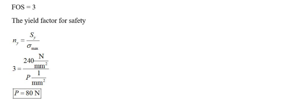
The mechanical component shown in the diagram is 200 mm wide and
10 mm thick and is made of aluminum that has a yield stress of 240
MPa. Calculate the maximum safe load P that can be applied if the
normal stress in the component must not exceed the material’s yield
stress. Include a factor of safety of 3.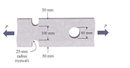
Homework Answers

Add Answer to:
The mechanical component shown in the diagram is 200 mm wide and
10 mm thick and...
A plate 92 mm wide, 184 mm long, and 11.04 mm thick is loaded in tension...
 A plate 92 mm wide, 184 mm long, and 11.04 mm thick is loaded in tension in the direction of the length. The plate contains a crack as shown in the figure below with the crack length of 147 mm. The material is steel with KC = 80 MPa (my(12) and Sy=950 MPa. 7.0 6.0 3.0 40 10 /b=05 1.0 2.0 10 02 0.6 0.8 w/braio Ignoring stress concentration, determine the maximum possible load that can be applied to the...
A plate 92 mm wide, 184 mm long, and 11.04 mm thick is loaded in tension...
 A plate 92 mm wide, 184 mm long, and 11.04 mm thick is loaded in tension in the direction of the length. The plate contains a crack as shown in the figure below with the crack length of 14.7 mm. The material is steel with KC= 80 MPa (m)(1/2) and Sy=950 MPa 7.0 6,0 5.0 4.0 3.0 /b=0.5 1.0 20 LO 0 02 06 OX 04 w/bratio Ignoring stress concentration, determine the maximum possible load that can be applied to...
A plate 95 mm wide, 190 mm long, and 11.4 mm thick is loaded in tension...
 A plate 95 mm wide, 190 mm long, and 11.4 mm thick is loaded in tension in the direction of the length. The plate contains a crack as shown in the figure below with the crack length of 15.2 mm. The material is steel with KIC= 80 MPa (m)(1/2) and Sy= 950 MPa. 6.0 5.0 4.0 3.0 h/b=0.5 1.0 2.0 1.0 0.2 0.4 a/b ratio Ignoring stress concentration, determine the maximum possible load that can be applied to the plate...
with steps please!!! Question3 Design a thick-walled metallic cylinder of a 200 mm internal diameter for an internal...
 with steps please!!!
Question3 Design a thick-walled metallic cylinder of a 200 mm internal diameter for an internal pressure of 30 MPa such as to provide a factor of safety of 3.0 against any yielding in the cylinder and a factor of safety of 4.0 against ultimate collapse. The yield stress of the material is 480 MPa Use both linear and non-linear stress distribution methods of calculation. Compare and discuss the results.
Question3 Design a thick-walled metallic cylinder of a...
with steps please!!!
Question3 Design a thick-walled metallic cylinder of a 200 mm internal diameter for an internal pressure of 30 MPa such as to provide a factor of safety of 3.0 against any yielding in the cylinder and a factor of safety of 4.0 against ultimate collapse. The yield stress of the material is 480 MPa Use both linear and non-linear stress distribution methods of calculation. Compare and discuss the results.
Question3 Design a thick-walled metallic cylinder of a...
a force p = 200 N is applied on a 25 mm thick bar with a...
 a force p = 200 N is applied on a 25 mm thick bar with a 30 mm
diameter hole on each end. a) what is the maximal average normal
stress in the bar and where does it occur?
Example 5 - Typical link A force P = 200 N is applied on a 25-mm thick bar with a 30-mm diameter hole on each end. a) What is the maximal average normal stress in the bar and where does it...
a force p = 200 N is applied on a 25 mm thick bar with a 30 mm
diameter hole on each end. a) what is the maximal average normal
stress in the bar and where does it occur?
Example 5 - Typical link A force P = 200 N is applied on a 25-mm thick bar with a 30-mm diameter hole on each end. a) What is the maximal average normal stress in the bar and where does it...
A cantilever spring made of SAE 4340 heat-treated steel is 50 mm thick. As shown in...
 A cantilever spring made of SAE 4340 heat-treated steel is 50 mm thick. As shown in the figure, the depth of the rectangular cross sec- tion is reduced from 80 mm to 40 mm using fillets at the transition A factor of safety of 2.5 with respect to fracture is specified for the spring. Determine the maximum safe moment M for the spring if: M 40 mm 80 mm (a) the fillet radius r is 4 mm (b) the fillet...
3.2 A steel tension bar 8-mm thick and 50-mm wide with an initial single- edge crack...
 3.2 A steel tension bar 8-mm thick and 50-mm wide with an initial single- edge crack of 10-mm long is subjected to an uniaxial stress o = 140 MPa. a) Determine the stress intensity factor K). Is the crack stable? b) Determine the critical crack size, and c) determine the critical load. Data: Kic = 60 MPaym. [Solution: a) 34 MPa, b) 31.1 mm, and c) 98.84 kN).
Question 3 Design a thick-walled metallic cylinder of a 200 mm internal diameter for an internal...
 Question 3 Design a thick-walled metallic cylinder of a 200 mm internal diameter for an internal pressure of 30 MPa such as to provide a factor of safety of 3.0 against any yielding in the cylinder and a factor of safety of 4.0 against ultimate collapse. The yield stress of the material is 480 MPa Use both linear and non-linear stress distribution methods of calculation. Compare and discuss the results.
Link OB is 20 mm wide and 10 mm thick and is made from low-carbon steel...
 Link OB is 20 mm wide and 10 mm thick and is made from low-carbon steel with Sy= 200 MPa. The pin joints are constructed with sufficient size and fit to provide good resistance to out-of-plane bending. Determine the factor of safety for out-of-plane buckling. 400 mm 800 mm where F=1250 N The factor of safety for out-of-plane buckling is 3.54.
Q2. The state of stress on the surface of part of an engineering component is shown...
 Q2. The state of stress on the surface of part of an engineering component is shown in Fig. 22. 94 MPa 51 MPa 25° 63 MPa Fig. Q2 - The State of Stress on the Surface of an Engineering Component (a) Using graph paper construct a Mohr's Stress Circle for the element and hence determine the magnitudes of the principal stresses and orientations of the principal planes. Clearly label these features on your diagram and sketch the state of stress...
 A plate 92 mm wide, 184 mm long, and 11.04 mm thick is loaded in tension in the direction of the length. The plate contains a crack as shown in the figure below with the crack length of 147 mm. The material is steel with KC = 80 MPa (my(12) and Sy=950 MPa. 7.0 6.0 3.0 40 10 /b=05 1.0 2.0 10 02 0.6 0.8 w/braio Ignoring stress concentration, determine the maximum possible load that can be applied to the...
 A plate 92 mm wide, 184 mm long, and 11.04 mm thick is loaded in tension in the direction of the length. The plate contains a crack as shown in the figure below with the crack length of 14.7 mm. The material is steel with KC= 80 MPa (m)(1/2) and Sy=950 MPa 7.0 6,0 5.0 4.0 3.0 /b=0.5 1.0 20 LO 0 02 06 OX 04 w/bratio Ignoring stress concentration, determine the maximum possible load that can be applied to...
 A plate 95 mm wide, 190 mm long, and 11.4 mm thick is loaded in tension in the direction of the length. The plate contains a crack as shown in the figure below with the crack length of 15.2 mm. The material is steel with KIC= 80 MPa (m)(1/2) and Sy= 950 MPa. 6.0 5.0 4.0 3.0 h/b=0.5 1.0 2.0 1.0 0.2 0.4 a/b ratio Ignoring stress concentration, determine the maximum possible load that can be applied to the plate...
 with steps please!!!
Question3 Design a thick-walled metallic cylinder of a 200 mm internal diameter for an internal pressure of 30 MPa such as to provide a factor of safety of 3.0 against any yielding in the cylinder and a factor of safety of 4.0 against ultimate collapse. The yield stress of the material is 480 MPa Use both linear and non-linear stress distribution methods of calculation. Compare and discuss the results.
Question3 Design a thick-walled metallic cylinder of a...
with steps please!!!
Question3 Design a thick-walled metallic cylinder of a 200 mm internal diameter for an internal pressure of 30 MPa such as to provide a factor of safety of 3.0 against any yielding in the cylinder and a factor of safety of 4.0 against ultimate collapse. The yield stress of the material is 480 MPa Use both linear and non-linear stress distribution methods of calculation. Compare and discuss the results.
Question3 Design a thick-walled metallic cylinder of a...
 a force p = 200 N is applied on a 25 mm thick bar with a 30 mm
diameter hole on each end. a) what is the maximal average normal
stress in the bar and where does it occur?
Example 5 - Typical link A force P = 200 N is applied on a 25-mm thick bar with a 30-mm diameter hole on each end. a) What is the maximal average normal stress in the bar and where does it...
a force p = 200 N is applied on a 25 mm thick bar with a 30 mm
diameter hole on each end. a) what is the maximal average normal
stress in the bar and where does it occur?
Example 5 - Typical link A force P = 200 N is applied on a 25-mm thick bar with a 30-mm diameter hole on each end. a) What is the maximal average normal stress in the bar and where does it...
 A cantilever spring made of SAE 4340 heat-treated steel is 50 mm thick. As shown in the figure, the depth of the rectangular cross sec- tion is reduced from 80 mm to 40 mm using fillets at the transition A factor of safety of 2.5 with respect to fracture is specified for the spring. Determine the maximum safe moment M for the spring if: M 40 mm 80 mm (a) the fillet radius r is 4 mm (b) the fillet...
 3.2 A steel tension bar 8-mm thick and 50-mm wide with an initial single- edge crack of 10-mm long is subjected to an uniaxial stress o = 140 MPa. a) Determine the stress intensity factor K). Is the crack stable? b) Determine the critical crack size, and c) determine the critical load. Data: Kic = 60 MPaym. [Solution: a) 34 MPa, b) 31.1 mm, and c) 98.84 kN).
 Question 3 Design a thick-walled metallic cylinder of a 200 mm internal diameter for an internal pressure of 30 MPa such as to provide a factor of safety of 3.0 against any yielding in the cylinder and a factor of safety of 4.0 against ultimate collapse. The yield stress of the material is 480 MPa Use both linear and non-linear stress distribution methods of calculation. Compare and discuss the results.
 Link OB is 20 mm wide and 10 mm thick and is made from low-carbon steel with Sy= 200 MPa. The pin joints are constructed with sufficient size and fit to provide good resistance to out-of-plane bending. Determine the factor of safety for out-of-plane buckling. 400 mm 800 mm where F=1250 N The factor of safety for out-of-plane buckling is 3.54.
 Q2. The state of stress on the surface of part of an engineering component is shown in Fig. 22. 94 MPa 51 MPa 25° 63 MPa Fig. Q2 - The State of Stress on the Surface of an Engineering Component (a) Using graph paper construct a Mohr's Stress Circle for the element and hence determine the magnitudes of the principal stresses and orientations of the principal planes. Clearly label these features on your diagram and sketch the state of stress...
Most questions answered within 3 hours.
-
Where is the error in this code sequence?
String s1 = "Hello";
String s2 = "ello";...
asked 10 months ago -
Financial data for Joel de Paris, Inc., for last year
follow:
Joel de Paris, Inc.
Balance...
asked 10 months ago -
Consider this reaction:
Al2(SO4)3 (aq)+ BaCl3
(aq) Al2Cl6 (aq)- +
3BaSO4(s) . What is the...
asked 10 months ago -
Suppose that Savneet is considering increasing her
recent random sample from 20 car rentals to 40...
asked 10 months ago -
Trucks arrive at an unloading terminal at an average rate of 120
per hour.
Trucks arrive...
asked 10 months ago -
Why are methanol and ethanol completely soluble in water while
octanol is not very little soluble....
asked 10 months ago -
A facilities manager at a university reads in a research report
that the mean amount of...
asked 10 months ago -
When the CuSO4 is rehydrated by adding water to the anhydrous
compound, is this an endothermic...
asked 10 months ago -
A ray of sunlight is passing from diamond into crown glass; the
angle of incidence is...
asked 10 months ago -
A block of mass 0.249 kg is placed on top of a light, vertical
spring of...
asked 10 months ago -
how do the kidneys compensate in the presences of acidosis
a) trigger hyperventilate
b) reserve acid...
asked 10 months ago -
Question 501 pts
The rental rate of capital to the firm increases. Which of the
following...
asked 10 months ago