
Homework Answers


Add Answer to:
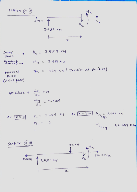
Draw the internal force diagrams for the system below. For full
credit, include all significant values....
Draw the internal force diagrams for the system below. For full credit, include all significant values....
 Draw the internal force diagrams for the system below. For full
credit, include all significant values.
7. Draw the internal force diagrams for the system below. For full credit, include all significant values. F2 = 80 [kip] F2 [kip] w ( Wz = 36 [kip/ft] 6 = 6 [ft] a=13 [ft B b (a+b)
Draw the internal force diagrams for the system below. For full
credit, include all significant values.
7. Draw the internal force diagrams for the system below. For full credit, include all significant values. F2 = 80 [kip] F2 [kip] w ( Wz = 36 [kip/ft] 6 = 6 [ft] a=13 [ft B b (a+b)
w1=12, w2=36,a=9,b=22. For the statically determinate system below, draw all three internal force diagrams (N, V,...
 w1=12, w2=36,a=9,b=22.
For the statically determinate system below, draw all three internal force diagrams (N, V, and M) and include all significant values. w1 w1 w2
w1=12, w2=36,a=9,b=22.
For the statically determinate system below, draw all three internal force diagrams (N, V, and M) and include all significant values. w1 w1 w2
a=9,b=22, w1=12, Ay=93.7,By=170.3,Bx=0. For the statically determinate system below, draw all three internal force diagrams (N,...
 a=9,b=22, w1=12, Ay=93.7,By=170.3,Bx=0.
For the statically determinate system below, draw all three internal force diagrams (N, V, and M) and include all significant values. w1
a=9,b=22, w1=12, Ay=93.7,By=170.3,Bx=0.
For the statically determinate system below, draw all three internal force diagrams (N, V, and M) and include all significant values. w1
Determine the support reactions and draw internal force (V, M) diagrams for the continuous beam shown...
 Determine the support reactions and draw internal force (V, M) diagrams for the continuous beam shown in the figure due to the uniformly distributed load and the support settlements of 15 mm at support B, 36 mm at support C and 18 mm at support at D. 32 kN/m о. В 15 mm Со. 36 mm 18 mm 5m - 5m 5m - E = 200 GPa 1 = 1705 x 10 mm
13. Draw shearing force and bending moment diagrams for the structure shown in figure below. (20...
 13. Draw shearing force and bending moment diagrams for the structure shown in figure below. (20 points) 30 kN/m 20 kN/nm 15 m 20 m
Draw shear force and bending moment diagrams for the following, giving all principal values. 50 KN...
 Draw shear force and bending moment diagrams for the
following, giving all principal values.
50 KN 40 KN 20 AN 30 AN 50 kNm 2m 2m 20 N 20KN kNm 4 m 10 KN 2 m 3 m
Draw shear force and bending moment diagrams for the
following, giving all principal values.
50 KN 40 KN 20 AN 30 AN 50 kNm 2m 2m 20 N 20KN kNm 4 m 10 KN 2 m 3 m
Name: Question 6 (25 Points) For the shown beam below, determine the following: 1) The internal forces at F (mid-point between C & D) 2) Draw the Shear Force and Bending Moment diagrams ID: Sec:...
 Name: Question 6 (25 Points) For the shown beam below, determine the following: 1) The internal forces at F (mid-point between C & D) 2) Draw the Shear Force and Bending Moment diagrams ID: Sec: (9 Points) (16 Points) 20 N 100 N N/m
Name: Question 6 (25 Points) For the shown beam below, determine the following: 1) The internal forces at F (mid-point between C & D) 2) Draw the Shear Force and Bending Moment diagrams ID: Sec: (9...
Name: Question 6 (25 Points) For the shown beam below, determine the following: 1) The internal forces at F (mid-point between C & D) 2) Draw the Shear Force and Bending Moment diagrams ID: Sec: (9 Points) (16 Points) 20 N 100 N N/m
Name: Question 6 (25 Points) For the shown beam below, determine the following: 1) The internal forces at F (mid-point between C & D) 2) Draw the Shear Force and Bending Moment diagrams ID: Sec: (9...
Determine the internal force shear force and moment at point c. ENGR 2301 Statics Spring 2014 Name Exam 3 Sbow all w...
 Determine the internal force shear force and moment at point
c.
ENGR 2301 Statics Spring 2014 Name Exam 3 Sbow all work for full credit. 1. Determine the internal normal force, shear force, and moment at point C in the simply supported beam. 5 kN 3 kN/m --15 m -15 m3m
Determine the internal force shear force and moment at point
c.
ENGR 2301 Statics Spring 2014 Name Exam 3 Sbow all work for full credit. 1. Determine the internal normal force, shear force, and moment at point C in the simply supported beam. 5 kN 3 kN/m --15 m -15 m3m
For the two frames given below Compute the Support Reactions Draw the Free Body Diagrams for...
 For the two frames given below Compute the Support Reactions Draw the Free Body Diagrams for all members, and joints with concentrated load or moment Draw the Bending Moment Diagram, Shear Force Diagram, and Axial Force Diagram using the sign conventions and labeling scheme taught in the class Draw the Qualitative Deflected Shape, clearly showing the Inflection Points, if any. 1. (50 points) 45 k Need FBD 3 k/ft 15 ft 2. (50 points) 15 kN/m F G 65 kN...
find 1) Draw shear force and bending moment diagrams for the beams subjected to the loadings...
 find
1) Draw shear force and bending moment diagrams for the beams subjected to the loadings shown below. Please show all your work SEN 25 N/m 45KM 10KN KN 15 2m 1 Im 2 3 m
find
1) Draw shear force and bending moment diagrams for the beams subjected to the loadings shown below. Please show all your work SEN 25 N/m 45KM 10KN KN 15 2m 1 Im 2 3 m
 Draw the internal force diagrams for the system below. For full
credit, include all significant values.
7. Draw the internal force diagrams for the system below. For full credit, include all significant values. F2 = 80 [kip] F2 [kip] w ( Wz = 36 [kip/ft] 6 = 6 [ft] a=13 [ft B b (a+b)
Draw the internal force diagrams for the system below. For full
credit, include all significant values.
7. Draw the internal force diagrams for the system below. For full credit, include all significant values. F2 = 80 [kip] F2 [kip] w ( Wz = 36 [kip/ft] 6 = 6 [ft] a=13 [ft B b (a+b)
 w1=12, w2=36,a=9,b=22.
For the statically determinate system below, draw all three internal force diagrams (N, V, and M) and include all significant values. w1 w1 w2
w1=12, w2=36,a=9,b=22.
For the statically determinate system below, draw all three internal force diagrams (N, V, and M) and include all significant values. w1 w1 w2
 a=9,b=22, w1=12, Ay=93.7,By=170.3,Bx=0.
For the statically determinate system below, draw all three internal force diagrams (N, V, and M) and include all significant values. w1
a=9,b=22, w1=12, Ay=93.7,By=170.3,Bx=0.
For the statically determinate system below, draw all three internal force diagrams (N, V, and M) and include all significant values. w1
 Determine the support reactions and draw internal force (V, M) diagrams for the continuous beam shown in the figure due to the uniformly distributed load and the support settlements of 15 mm at support B, 36 mm at support C and 18 mm at support at D. 32 kN/m о. В 15 mm Со. 36 mm 18 mm 5m - 5m 5m - E = 200 GPa 1 = 1705 x 10 mm
 13. Draw shearing force and bending moment diagrams for the structure shown in figure below. (20 points) 30 kN/m 20 kN/nm 15 m 20 m
 Draw shear force and bending moment diagrams for the
following, giving all principal values.
50 KN 40 KN 20 AN 30 AN 50 kNm 2m 2m 20 N 20KN kNm 4 m 10 KN 2 m 3 m
Draw shear force and bending moment diagrams for the
following, giving all principal values.
50 KN 40 KN 20 AN 30 AN 50 kNm 2m 2m 20 N 20KN kNm 4 m 10 KN 2 m 3 m
 Name: Question 6 (25 Points) For the shown beam below, determine the following: 1) The internal forces at F (mid-point between C & D) 2) Draw the Shear Force and Bending Moment diagrams ID: Sec: (9 Points) (16 Points) 20 N 100 N N/m
Name: Question 6 (25 Points) For the shown beam below, determine the following: 1) The internal forces at F (mid-point between C & D) 2) Draw the Shear Force and Bending Moment diagrams ID: Sec: (9...
Name: Question 6 (25 Points) For the shown beam below, determine the following: 1) The internal forces at F (mid-point between C & D) 2) Draw the Shear Force and Bending Moment diagrams ID: Sec: (9 Points) (16 Points) 20 N 100 N N/m
Name: Question 6 (25 Points) For the shown beam below, determine the following: 1) The internal forces at F (mid-point between C & D) 2) Draw the Shear Force and Bending Moment diagrams ID: Sec: (9...
 Determine the internal force shear force and moment at point
c.
ENGR 2301 Statics Spring 2014 Name Exam 3 Sbow all work for full credit. 1. Determine the internal normal force, shear force, and moment at point C in the simply supported beam. 5 kN 3 kN/m --15 m -15 m3m
Determine the internal force shear force and moment at point
c.
ENGR 2301 Statics Spring 2014 Name Exam 3 Sbow all work for full credit. 1. Determine the internal normal force, shear force, and moment at point C in the simply supported beam. 5 kN 3 kN/m --15 m -15 m3m
 For the two frames given below Compute the Support Reactions Draw the Free Body Diagrams for all members, and joints with concentrated load or moment Draw the Bending Moment Diagram, Shear Force Diagram, and Axial Force Diagram using the sign conventions and labeling scheme taught in the class Draw the Qualitative Deflected Shape, clearly showing the Inflection Points, if any. 1. (50 points) 45 k Need FBD 3 k/ft 15 ft 2. (50 points) 15 kN/m F G 65 kN...
 find
1) Draw shear force and bending moment diagrams for the beams subjected to the loadings shown below. Please show all your work SEN 25 N/m 45KM 10KN KN 15 2m 1 Im 2 3 m
find
1) Draw shear force and bending moment diagrams for the beams subjected to the loadings shown below. Please show all your work SEN 25 N/m 45KM 10KN KN 15 2m 1 Im 2 3 m
Most questions answered within 3 hours.
-
Where is the error in this code sequence?
String s1 = "Hello";
String s2 = "ello";...
asked 10 months ago -
Financial data for Joel de Paris, Inc., for last year
follow:
Joel de Paris, Inc.
Balance...
asked 10 months ago -
Consider this reaction:
Al2(SO4)3 (aq)+ BaCl3
(aq) Al2Cl6 (aq)- +
3BaSO4(s) . What is the...
asked 10 months ago -
Suppose that Savneet is considering increasing her
recent random sample from 20 car rentals to 40...
asked 10 months ago -
Trucks arrive at an unloading terminal at an average rate of 120
per hour.
Trucks arrive...
asked 10 months ago -
Why are methanol and ethanol completely soluble in water while
octanol is not very little soluble....
asked 10 months ago -
A facilities manager at a university reads in a research report
that the mean amount of...
asked 10 months ago -
When the CuSO4 is rehydrated by adding water to the anhydrous
compound, is this an endothermic...
asked 10 months ago -
A ray of sunlight is passing from diamond into crown glass; the
angle of incidence is...
asked 10 months ago -
A block of mass 0.249 kg is placed on top of a light, vertical
spring of...
asked 10 months ago -
how do the kidneys compensate in the presences of acidosis
a) trigger hyperventilate
b) reserve acid...
asked 10 months ago -
Question 501 pts
The rental rate of capital to the firm increases. Which of the
following...
asked 10 months ago