

Homework Answers

Add Answer to:
An LRC circuit is connected to a 12.5 kHz, 735-V (rms) source, L = 26.0 mH,...
Problem 21.64 An LRC circuit is connected to a 12.5-kHz, 735-V (rms) source, L = 26.0...
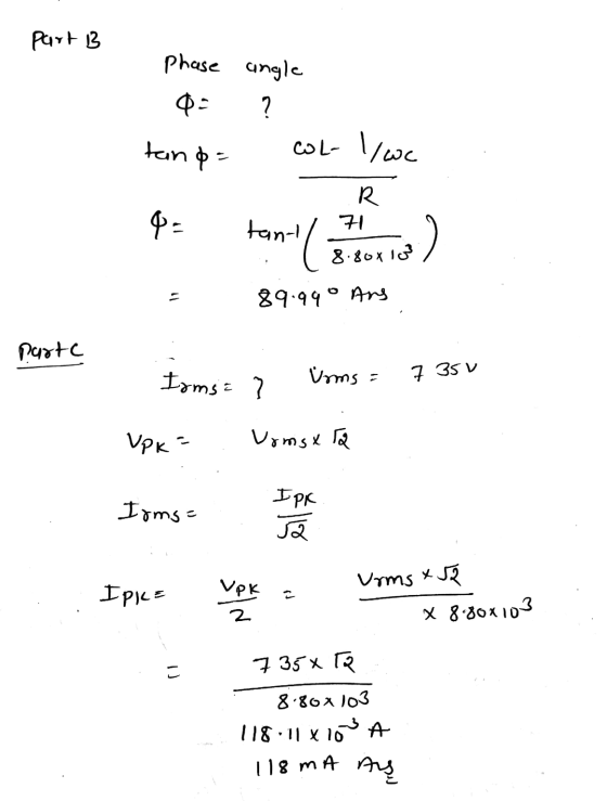
 Problem 21.64 An LRC circuit is connected to a 12.5-kHz, 735-V (rms) source, L = 26.0 mH, R =8.80 kN, and C = 6450 pF. Part B Determine the phase angle Express your answer using three significant figures. 190 AED -0.008068 Submit Previous Answers Request Answer * Incorrect; Try Again; 3 attempts remaining Part C Determine rms current Express your answer to three significant figures and include the appropriate units. ? XS 010 x 10" DE 1.- 118.11.10 А You...
An LRC circuit is connected to a 10.5-kHz, 725-V (ms) source, L = 26.0 mH, R...
 An LRC circuit is connected to a 10.5-kHz, 725-V (ms) source, L = 26.0 mH, R = 8.20 kN and C = 6250 pF. Part A Determine the total impedance. xpress your answer to three significant figures and include the appropriate units. ? HAR Value O Units 2. Submit Request Answer Part B Determine the phase angle. Express your answer using three significant figures. 90 AED Om ? Submit Request Answer Part C Determine rms current. Express your answer to...
7 of 10 Constants An LRC circuit is connected to a 11.5-kHz, 785-V (rms source, L...
 7 of 10 Constants An LRC circuit is connected to a 11.5-kHz, 785-V (rms source, L 28.0 mH, R 8.80 k, and C 6150 pF Part A Determine the total impedance. xpress your answer to three significant figures and include the appropriate units. Z- 8.80 k2 Correct Part B Determine the phase angle. Express your answer using three significant figures. 2.04 Request Answer Incorrect; Try Again; 5 attempts remaining Part C Determine rms current. Express your answer to three significant...
An LRC circuit is connected to a 12.0-kHz, 785-V (rms) source, L = 25.0 mH ,...
An LRC circuit is connected to a 12.0-kHz, 785-V (rms) source, L = 25.0 mH , R = 8.30 kΩ , and C = 6250 pF Part A: Determine the total impedance. Part B: Determine the phase angle. Part C: Determine rms current.
Consider the circuit shown in (Figure 1). Suppose that V, = 415 0°V (rms). 4 Ω...
 Consider the circuit shown in (Figure 1). Suppose that V, = 415 0°V (rms). 4 Ω ν j3ΩΙ 120 Ω + j90 Ω Source- Line - Load Find the average power dissipated in the line in the figure. Express your answer to three significant figures and include the appropriate units. t НА ? ? P= Value Units Find the capacitive reactance that, when connected in parallel, with the load will make the load look purely resistive. Express your answer to...
Problem 4.7 Consider the circuit shown in (Figure 1). The source voltage v1 is 40 V....
 Problem 4.7 Consider the circuit shown in (Figure 1). The source voltage v1 is 40 V. Resistance R1, R2 and R3 are 5 ,120 and 15 , respectively. The source current I is 25 mA Part A Find the power developed by the current source I in the circuit. Express your answer to three significant figures and include the appropriate units. НА Value Units Рi 3 Request Answer Submit Part B Figure 1 of 1 Find the power developed by...
\ Problem 6 Consider the circuit shown in (Figure 1). Suppose that V, = 480_0°V (rms)....
 \
Problem 6 Consider the circuit shown in (Figure 1). Suppose that V, = 480_0°V (rms). Part A Find the average power dissipated in the line in the figure Express your answer three significant figures and include the appropriate units. HHA ? P = Value Units Submit Request Answer Part B Figure 1 of 1 > Find the capacitive reactance that, when connected in parallel, with the load will make the load look purely resistive. Express your answer three significant...
\
Problem 6 Consider the circuit shown in (Figure 1). Suppose that V, = 480_0°V (rms). Part A Find the average power dissipated in the line in the figure Express your answer three significant figures and include the appropriate units. HHA ? P = Value Units Submit Request Answer Part B Figure 1 of 1 > Find the capacitive reactance that, when connected in parallel, with the load will make the load look purely resistive. Express your answer three significant...
In the circuit in (Figure 1) the voltage and current expressions are v=48e-25 V, t> 0...
 In the circuit in (Figure 1) the voltage and current expressions are v=48e-25 V, t> 0 i= 20e mA, tot Part A -250 Find R Express your answer to three significant figures and include the appropriate units. НА ? R= Value Units Submit Request Answer Part B Find C. Express your answer to three significant figures and include the appropriate units. НА Figure < 1 of 1 C= Value Units i Submit Request Answer + Part C V R Find...
A 15.0 mH inductor produces a peak voltage of 10.6 V. s connected across an AC...
 A 15.0 mH inductor produces a peak voltage of 10.6 V. s connected across an AC generator that Part A What is the peak current through the inductor if the emf frequency is 100 Hz? Express your answer to two significant figures and include the appropriate units. HA Value IL = Units Request Answer Submit Part B What is the peak current through the inductor if the emf frequency is 100 kHz? Express your answer to two significant figures and...
Please answer all parts Consider the circuit shown in (Figure 1). Suppose that Ve = 50070°V...
 Please answer all parts
Consider the circuit shown in (Figure 1). Suppose that Ve = 50070°V (rms). Express your answer to three significant figures and include the appropriate units. View Available Hint(s) IT HA ? 21 = Value Units Submit Part D Find the average power dissipated in the line when the capacitive reactance is connected across the load. Express your answer to three significant figures and include the appropriate units. THA th ? P- Value Units Submit Request Answer...
Please answer all parts
Consider the circuit shown in (Figure 1). Suppose that Ve = 50070°V (rms). Express your answer to three significant figures and include the appropriate units. View Available Hint(s) IT HA ? 21 = Value Units Submit Part D Find the average power dissipated in the line when the capacitive reactance is connected across the load. Express your answer to three significant figures and include the appropriate units. THA th ? P- Value Units Submit Request Answer...
 Problem 21.64 An LRC circuit is connected to a 12.5-kHz, 735-V (rms) source, L = 26.0 mH, R =8.80 kN, and C = 6450 pF. Part B Determine the phase angle Express your answer using three significant figures. 190 AED -0.008068 Submit Previous Answers Request Answer * Incorrect; Try Again; 3 attempts remaining Part C Determine rms current Express your answer to three significant figures and include the appropriate units. ? XS 010 x 10" DE 1.- 118.11.10 А You...
 An LRC circuit is connected to a 10.5-kHz, 725-V (ms) source, L = 26.0 mH, R = 8.20 kN and C = 6250 pF. Part A Determine the total impedance. xpress your answer to three significant figures and include the appropriate units. ? HAR Value O Units 2. Submit Request Answer Part B Determine the phase angle. Express your answer using three significant figures. 90 AED Om ? Submit Request Answer Part C Determine rms current. Express your answer to...
 7 of 10 Constants An LRC circuit is connected to a 11.5-kHz, 785-V (rms source, L 28.0 mH, R 8.80 k, and C 6150 pF Part A Determine the total impedance. xpress your answer to three significant figures and include the appropriate units. Z- 8.80 k2 Correct Part B Determine the phase angle. Express your answer using three significant figures. 2.04 Request Answer Incorrect; Try Again; 5 attempts remaining Part C Determine rms current. Express your answer to three significant...
 Consider the circuit shown in (Figure 1). Suppose that V, = 415 0°V (rms). 4 Ω ν j3ΩΙ 120 Ω + j90 Ω Source- Line - Load Find the average power dissipated in the line in the figure. Express your answer to three significant figures and include the appropriate units. t НА ? ? P= Value Units Find the capacitive reactance that, when connected in parallel, with the load will make the load look purely resistive. Express your answer to...
 Problem 4.7 Consider the circuit shown in (Figure 1). The source voltage v1 is 40 V. Resistance R1, R2 and R3 are 5 ,120 and 15 , respectively. The source current I is 25 mA Part A Find the power developed by the current source I in the circuit. Express your answer to three significant figures and include the appropriate units. НА Value Units Рi 3 Request Answer Submit Part B Figure 1 of 1 Find the power developed by...
 \
Problem 6 Consider the circuit shown in (Figure 1). Suppose that V, = 480_0°V (rms). Part A Find the average power dissipated in the line in the figure Express your answer three significant figures and include the appropriate units. HHA ? P = Value Units Submit Request Answer Part B Figure 1 of 1 > Find the capacitive reactance that, when connected in parallel, with the load will make the load look purely resistive. Express your answer three significant...
\
Problem 6 Consider the circuit shown in (Figure 1). Suppose that V, = 480_0°V (rms). Part A Find the average power dissipated in the line in the figure Express your answer three significant figures and include the appropriate units. HHA ? P = Value Units Submit Request Answer Part B Figure 1 of 1 > Find the capacitive reactance that, when connected in parallel, with the load will make the load look purely resistive. Express your answer three significant...
 In the circuit in (Figure 1) the voltage and current expressions are v=48e-25 V, t> 0 i= 20e mA, tot Part A -250 Find R Express your answer to three significant figures and include the appropriate units. НА ? R= Value Units Submit Request Answer Part B Find C. Express your answer to three significant figures and include the appropriate units. НА Figure < 1 of 1 C= Value Units i Submit Request Answer + Part C V R Find...
 A 15.0 mH inductor produces a peak voltage of 10.6 V. s connected across an AC generator that Part A What is the peak current through the inductor if the emf frequency is 100 Hz? Express your answer to two significant figures and include the appropriate units. HA Value IL = Units Request Answer Submit Part B What is the peak current through the inductor if the emf frequency is 100 kHz? Express your answer to two significant figures and...
 Please answer all parts
Consider the circuit shown in (Figure 1). Suppose that Ve = 50070°V (rms). Express your answer to three significant figures and include the appropriate units. View Available Hint(s) IT HA ? 21 = Value Units Submit Part D Find the average power dissipated in the line when the capacitive reactance is connected across the load. Express your answer to three significant figures and include the appropriate units. THA th ? P- Value Units Submit Request Answer...
Please answer all parts
Consider the circuit shown in (Figure 1). Suppose that Ve = 50070°V (rms). Express your answer to three significant figures and include the appropriate units. View Available Hint(s) IT HA ? 21 = Value Units Submit Part D Find the average power dissipated in the line when the capacitive reactance is connected across the load. Express your answer to three significant figures and include the appropriate units. THA th ? P- Value Units Submit Request Answer...
Most questions answered within 3 hours.
-
Where is the error in this code sequence?
String s1 = "Hello";
String s2 = "ello";...
asked 11 months ago -
Financial data for Joel de Paris, Inc., for last year
follow:
Joel de Paris, Inc.
Balance...
asked 11 months ago -
Consider this reaction:
Al2(SO4)3 (aq)+ BaCl3
(aq) Al2Cl6 (aq)- +
3BaSO4(s) . What is the...
asked 11 months ago -
Suppose that Savneet is considering increasing her
recent random sample from 20 car rentals to 40...
asked 11 months ago -
Trucks arrive at an unloading terminal at an average rate of 120
per hour.
Trucks arrive...
asked 11 months ago -
Why are methanol and ethanol completely soluble in water while
octanol is not very little soluble....
asked 11 months ago -
A facilities manager at a university reads in a research report
that the mean amount of...
asked 11 months ago -
When the CuSO4 is rehydrated by adding water to the anhydrous
compound, is this an endothermic...
asked 11 months ago -
A ray of sunlight is passing from diamond into crown glass; the
angle of incidence is...
asked 11 months ago -
A block of mass 0.249 kg is placed on top of a light, vertical
spring of...
asked 11 months ago -
how do the kidneys compensate in the presences of acidosis
a) trigger hyperventilate
b) reserve acid...
asked 11 months ago -
Question 501 pts
The rental rate of capital to the firm increases. Which of the
following...
asked 11 months ago