
Homework Answers

Add Answer to:
QUESTION 1 B A. B. F E (a) (b) Figure 1 Consider the combinational logic circuits...
QUESTION 2 The following program is written in the assembly language of 8085 processor: LXI B,...
 QUESTION 2 The following program is written in the assembly language of 8085 processor: LXI B, 20DF LXI H, 2B44 MOV A, C SUBB MOV A, L ADDH INX B DCXH HLT (a) Complete Table 1 with the machine codes and memory addresses for the whole program. [6 marks] (b) Determine the total number of bytes needed to execute the whole program. [1 mark] (c) State final value of all registers involved in the program. [3 marks)
QUESTION 1 B. A В. F E (a) (b) Figure 1 Consider the combinational logic circuits...
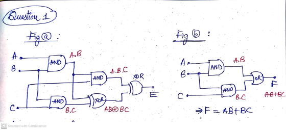
 QUESTION 1 B. A В. F E (a) (b) Figure 1 Consider the combinational logic circuits shown in Figure 1 (a) and Figure 1 (b). Prove that the two-logic circuit functions the same where the output expression, E equals the output expression, F; given the same inputs (A, B and C). [10 marks]
Figure 1 shows a logic circuit with output F. A с D F B Figure 1...
 Figure 1 shows a logic circuit with output F. A с D F B Figure 1 (a) Without simplification, determine the logic expression for F. (b) Simplify the expression using Boolean algebra. (c) Sketch the output waveform, F in Figure 2. A B с F Figure 2
1. An application of prepositional logic is the design of combinational circuits used in digital systems....
 1. An application of prepositional logic is the design
of combinational circuits used in digital systems. Using inputs
(statements) a1, b1,ao. Determine the outputs P, Q, and
R in figure 2 above
ii) Assuming P is true(“on”), what will be the output R of this
circuit
b) Given the domain of discourse is Real
numbers?
1c) The static force balance on three masses yields the following
system of equations:
(A+ B +C) x – By –Cz = G
–Bx +(B+D)y...
1. An application of prepositional logic is the design
of combinational circuits used in digital systems. Using inputs
(statements) a1, b1,ao. Determine the outputs P, Q, and
R in figure 2 above
ii) Assuming P is true(“on”), what will be the output R of this
circuit
b) Given the domain of discourse is Real
numbers?
1c) The static force balance on three masses yields the following
system of equations:
(A+ B +C) x – By –Cz = G
–Bx +(B+D)y...
1. Consider the code sequence: C= A + B D= A-E F= C+ D Assume the...
1. Consider the code sequence: C= A + B D= A-E F= C+ D Assume the values A, B, C, D, E, and F reside in memory. For each Architecture I. Accumulator Architecture II. Memory- Register Architecture III. Register-Register Architecture write the code assuming the instruction codes (opcode) are 8 bits, memory addresses are 32 bits, and register addresses are 6 bits and CPU has 64 Registers; and create a table which specifies: – The execution sequence – The variables...
Question 10 (5 marks) A combinational logic circuit is shown in Figure 3 along with a timing diagram. a) The output waveform (X) shown in the timing diagram is not correct for the circuit shown....
 Question 10 (5 marks) A combinational logic circuit is shown in Figure 3 along with a timing diagram. a) The output waveform (X) shown in the timing diagram is not correct for the circuit shown. Draw the correct waveform. (2 marks) b) The output waveform shown is the result of incorrect implementation of the circuit gates has been replaced by another type of gate. Which gate has been replaced and what is the replacement gate? Explain your answer. (3 marks)...
EE 210 Digital Logic Experiment 3 - Basic Combinational Logic: Adjacency Tester- Simulation only. In this...
 EE 210 Digital Logic Experiment 3 - Basic Combinational Logic: Adjacency Tester- Simulation only. In this experiment, the student will design and simulate a minimal AND, OR and INVERTER circuit, with 4 input variables A, B, C, and D, and output F, that will produce a logic 1 output whenever two adjacent input variables are 1s. In this context, the A and D variables are also treated as being adjacent variables. See the partially filled-in Truth Table below, for more...
computer orgnazation Given below are block/circuit diagrams of combinational circuits in Figures 1 and 2. a)...
 computer orgnazation
Given below are block/circuit diagrams of combinational circuits in Figures 1 and 2. a) Obtain the Truth Table for the output X (A, B, C, D) where A, B, C are the selector variables and D is the input given to the lines in Figure 1. What is the name of the circuit? [1.5] b) Write the expression for X (A, B, C, D) for Figure 1. Also write Tv (A,B,C,D) [2] c) In Figure 2, what is...
computer orgnazation
Given below are block/circuit diagrams of combinational circuits in Figures 1 and 2. a) Obtain the Truth Table for the output X (A, B, C, D) where A, B, C are the selector variables and D is the input given to the lines in Figure 1. What is the name of the circuit? [1.5] b) Write the expression for X (A, B, C, D) for Figure 1. Also write Tv (A,B,C,D) [2] c) In Figure 2, what is...
Title: Combinational Circuit Design and Simulation Objectives: a. b. c. Design combinational circuit Verify design with...
 Title: Combinational Circuit Design and Simulation Objectives: a. b. c. Design combinational circuit Verify design with simulation Verify design with laboratory test data Materials Needed IBM Compatible computer, PSpice software, IC Chips (as needed), Data Switches, 4702 (1), LED (1). Pre-Lab: Problem Statement The four parameters in a chemical process control system to be monitored are temperature (T), pressure (P), flow (F), and level (L) of the fluid. The parameters are monitored by sensor circuits that produce a High logic...
Question 1 Digital Electronics and Combinational Logic 1a) Analog and Digital Electronics i. Write either "digital"...
 Question 1 Digital Electronics and Combinational Logic 1a) Analog and Digital Electronics i. Write either "digital" or "analog" in this to indicate whether the property in that row is - typical of digital electronics or analog electronics. The first row has been completed as an example. Property Digital/Analog Difficult, manual circuit design Analog Continuous valued signals Tolerant of electrical noise Circuit state tends to leak Intolerant of component variations ii. In older cars the timing of the electrical pulses to...
 QUESTION 2 The following program is written in the assembly language of 8085 processor: LXI B, 20DF LXI H, 2B44 MOV A, C SUBB MOV A, L ADDH INX B DCXH HLT (a) Complete Table 1 with the machine codes and memory addresses for the whole program. [6 marks] (b) Determine the total number of bytes needed to execute the whole program. [1 mark] (c) State final value of all registers involved in the program. [3 marks)
 QUESTION 1 B. A В. F E (a) (b) Figure 1 Consider the combinational logic circuits shown in Figure 1 (a) and Figure 1 (b). Prove that the two-logic circuit functions the same where the output expression, E equals the output expression, F; given the same inputs (A, B and C). [10 marks]
 Figure 1 shows a logic circuit with output F. A с D F B Figure 1 (a) Without simplification, determine the logic expression for F. (b) Simplify the expression using Boolean algebra. (c) Sketch the output waveform, F in Figure 2. A B с F Figure 2
 1. An application of prepositional logic is the design
of combinational circuits used in digital systems. Using inputs
(statements) a1, b1,ao. Determine the outputs P, Q, and
R in figure 2 above
ii) Assuming P is true(“on”), what will be the output R of this
circuit
b) Given the domain of discourse is Real
numbers?
1c) The static force balance on three masses yields the following
system of equations:
(A+ B +C) x – By –Cz = G
–Bx +(B+D)y...
1. An application of prepositional logic is the design
of combinational circuits used in digital systems. Using inputs
(statements) a1, b1,ao. Determine the outputs P, Q, and
R in figure 2 above
ii) Assuming P is true(“on”), what will be the output R of this
circuit
b) Given the domain of discourse is Real
numbers?
1c) The static force balance on three masses yields the following
system of equations:
(A+ B +C) x – By –Cz = G
–Bx +(B+D)y...
 Question 10 (5 marks) A combinational logic circuit is shown in Figure 3 along with a timing diagram. a) The output waveform (X) shown in the timing diagram is not correct for the circuit shown. Draw the correct waveform. (2 marks) b) The output waveform shown is the result of incorrect implementation of the circuit gates has been replaced by another type of gate. Which gate has been replaced and what is the replacement gate? Explain your answer. (3 marks)...
 EE 210 Digital Logic Experiment 3 - Basic Combinational Logic: Adjacency Tester- Simulation only. In this experiment, the student will design and simulate a minimal AND, OR and INVERTER circuit, with 4 input variables A, B, C, and D, and output F, that will produce a logic 1 output whenever two adjacent input variables are 1s. In this context, the A and D variables are also treated as being adjacent variables. See the partially filled-in Truth Table below, for more...
 computer orgnazation
Given below are block/circuit diagrams of combinational circuits in Figures 1 and 2. a) Obtain the Truth Table for the output X (A, B, C, D) where A, B, C are the selector variables and D is the input given to the lines in Figure 1. What is the name of the circuit? [1.5] b) Write the expression for X (A, B, C, D) for Figure 1. Also write Tv (A,B,C,D) [2] c) In Figure 2, what is...
computer orgnazation
Given below are block/circuit diagrams of combinational circuits in Figures 1 and 2. a) Obtain the Truth Table for the output X (A, B, C, D) where A, B, C are the selector variables and D is the input given to the lines in Figure 1. What is the name of the circuit? [1.5] b) Write the expression for X (A, B, C, D) for Figure 1. Also write Tv (A,B,C,D) [2] c) In Figure 2, what is...
 Title: Combinational Circuit Design and Simulation Objectives: a. b. c. Design combinational circuit Verify design with simulation Verify design with laboratory test data Materials Needed IBM Compatible computer, PSpice software, IC Chips (as needed), Data Switches, 4702 (1), LED (1). Pre-Lab: Problem Statement The four parameters in a chemical process control system to be monitored are temperature (T), pressure (P), flow (F), and level (L) of the fluid. The parameters are monitored by sensor circuits that produce a High logic...
 Question 1 Digital Electronics and Combinational Logic 1a) Analog and Digital Electronics i. Write either "digital" or "analog" in this to indicate whether the property in that row is - typical of digital electronics or analog electronics. The first row has been completed as an example. Property Digital/Analog Difficult, manual circuit design Analog Continuous valued signals Tolerant of electrical noise Circuit state tends to leak Intolerant of component variations ii. In older cars the timing of the electrical pulses to...
Most questions answered within 3 hours.
-
Where is the error in this code sequence?
String s1 = "Hello";
String s2 = "ello";...
asked 10 months ago -
Financial data for Joel de Paris, Inc., for last year
follow:
Joel de Paris, Inc.
Balance...
asked 10 months ago -
Consider this reaction:
Al2(SO4)3 (aq)+ BaCl3
(aq) Al2Cl6 (aq)- +
3BaSO4(s) . What is the...
asked 10 months ago -
Suppose that Savneet is considering increasing her
recent random sample from 20 car rentals to 40...
asked 10 months ago -
Trucks arrive at an unloading terminal at an average rate of 120
per hour.
Trucks arrive...
asked 10 months ago -
Why are methanol and ethanol completely soluble in water while
octanol is not very little soluble....
asked 10 months ago -
A facilities manager at a university reads in a research report
that the mean amount of...
asked 10 months ago -
When the CuSO4 is rehydrated by adding water to the anhydrous
compound, is this an endothermic...
asked 10 months ago -
A ray of sunlight is passing from diamond into crown glass; the
angle of incidence is...
asked 10 months ago -
A block of mass 0.249 kg is placed on top of a light, vertical
spring of...
asked 10 months ago -
how do the kidneys compensate in the presences of acidosis
a) trigger hyperventilate
b) reserve acid...
asked 10 months ago -
Question 501 pts
The rental rate of capital to the firm increases. Which of the
following...
asked 10 months ago