
Homework Answers


Add Answer to:
.
a) Consider the control system in Figure 2(a). Determine the transient response characteristics (rise time,...
Question 2 a) Consider the control system in Figure 2(a). Determine the transient response characteristics (rise...
 Question 2 a) Consider the control system in Figure 2(a). Determine the transient response characteristics (rise time, peak time, maximum overshoot and settling time) and the steady state error for the system. (2 marks) b) To improve the relative stability, the tachometer feedback are employed as shown in Figure 2b). i Determine the value in so that the damping ratio of the system is 0.5. (1 % marks) From the result obtained in , evaluate the transient response characteristics (rise...
a) Consider the control system in Figure 2(a). Determine the transient response characteristics (rise time, peak...
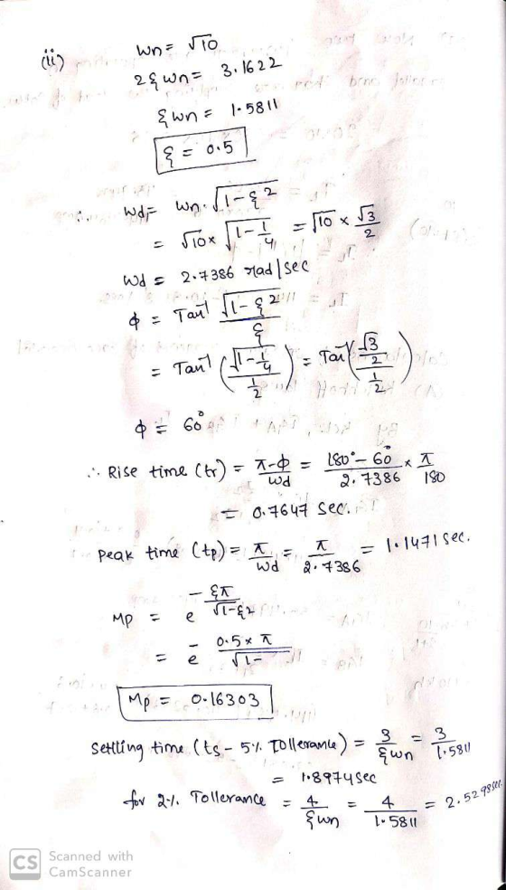
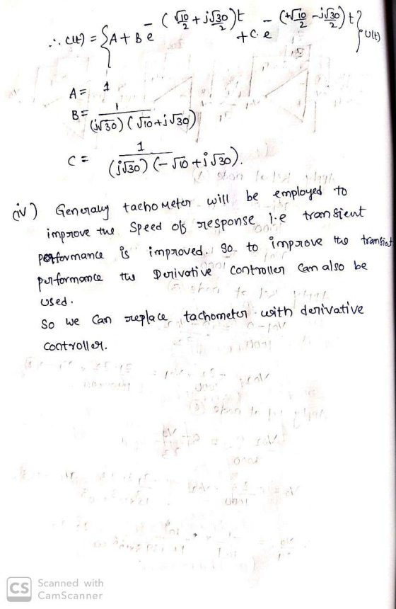
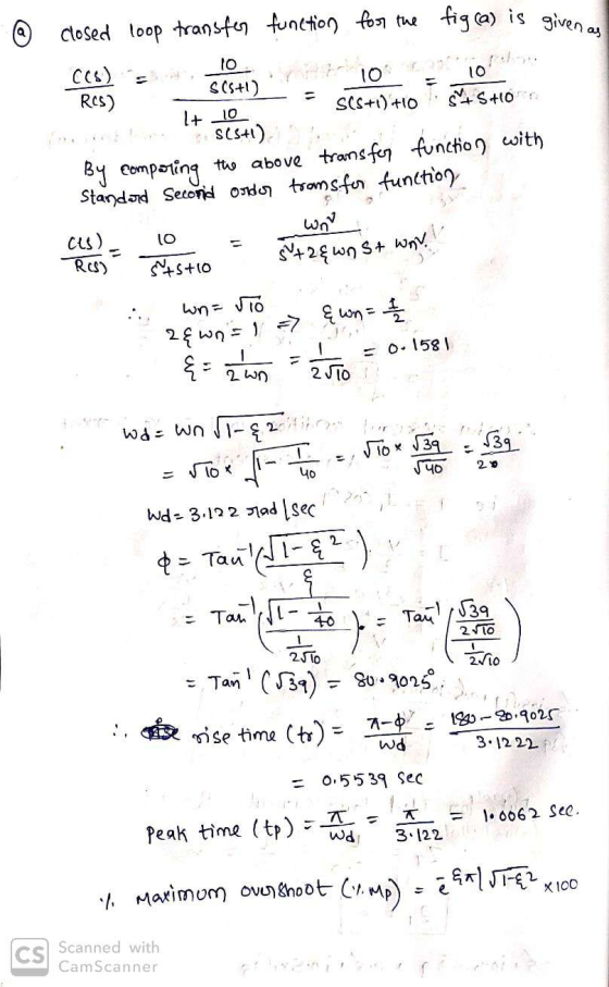
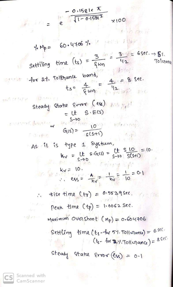
 a) Consider the control system in Figure 2(a). Determine the transient response characteristics (rise time, peak time, maximum overshoot and settling time) and the steady state error for the system. (2 marks) b) To improve the relative stability, the tachometer feedback are employed as shown in Figure 2(b). i Determine the value K, so that the damping ratio of the system is 0.5. (1 % marks) ii. From the result obtained in (), evaluate the transient response characteristics (rise time,...
Question 2 a) Consider the control system in Figure 2(a). Determine the transient response characteristics (rise...
 Question 2 a) Consider the control system in Figure 2(a). Determine the transient response characteristics (rise time, peak time, maximum overshoot and settling time) and the steady state error for the system. (2 marks) b) To improve the relative stability, the tachometer feedback are employed as shown in Figure 2(b). i Determine the value Kso that the damping ratio of the system is 0.5. (1 % marks) i. From the result obtained in (), evaluate the transient response characteristics (rise...
a) Consider the control system in Figure 2(a). Determine the transient response characteristics (rise time, peak...
 a) Consider the control system in Figure 2(a). Determine the transient response characteristics (rise time, peak time, maximum overshoot and settling time) and the steady state error for the system. (2 marks) b) To improve the relative stability, the tachometer feedback are employed as shown in Figure 2(b). i. Determine the value Kn so that the damping ratio of the system is 0.5. (1 22 marks) ii. iii. From the result obtained in (i), evaluate the transient response characteristics (rise...
Question 2 a) Consider the control system in Figure 2(a). Determine the transient response characteristics (rise...
 Question 2 a) Consider the control system in Figure 2(a). Determine the transient response characteristics (rise time, peak time, maximum overshoot and settling time) and the steady state error for the system. (2 marks) b) To improve the relative stability, the tachometer feedback are employed as shown in Figure 2(b). Determine the value K, so that the damping ratio of the system is 0.5. (1 % marks) i. From the result obtained in (), evaluate the transient response characteristics (rise...
question 2 Question 2 a) Consider the control system in Figure 2(a). Determine the transient response...
 question 2
Question 2 a) Consider the control system in Figure 2(a). Determine the transient response characteristics (rise time, peak time, maximum overshoot and settling time) and the steady state error for the system (2 marks) b) To improve the relative stability, the tachometer feedback are employed as shown in Figure 2(b). Determine the value Kin so that the damping ratio of the system is 0.5. (1 % marks) it. From the result obtained in 0. evaluate the transient response...
question 2
Question 2 a) Consider the control system in Figure 2(a). Determine the transient response characteristics (rise time, peak time, maximum overshoot and settling time) and the steady state error for the system (2 marks) b) To improve the relative stability, the tachometer feedback are employed as shown in Figure 2(b). Determine the value Kin so that the damping ratio of the system is 0.5. (1 % marks) it. From the result obtained in 0. evaluate the transient response...
QUICK UPVOTE: As a control system engineer you have been asked to design a controller that...
 QUICK UPVOTE:
As a control system engineer you have been asked to design a controller that would improve the error and the transient response for the unity feedback system below. The proposed solution must be cost-effective, so consider a passive network-based compensator. The transient response of the closed-loop transfer function to a ramp input has a 30% overshoot (%OS = 30) and a settling time Ts= 2.73 seconds. You need to decrease the peak time by a factor of 2,...
QUICK UPVOTE:
As a control system engineer you have been asked to design a controller that would improve the error and the transient response for the unity feedback system below. The proposed solution must be cost-effective, so consider a passive network-based compensator. The transient response of the closed-loop transfer function to a ramp input has a 30% overshoot (%OS = 30) and a settling time Ts= 2.73 seconds. You need to decrease the peak time by a factor of 2,...
2. You are given the motor whose transfer function is shown in Figure 2(a). s) e(s) Amplifier Mot...
 Control system
2. You are given the motor whose transfer function is shown in Figure 2(a). s) e(s) Amplifier Motor C(s) 15 Tachometer Кр Figure 2 a) If this motor were the forward transfer function of a unity feedback system, calculate the percent overshoot and settling time that could be expected. b) You want to improve the closed-loop response. Since the motor constants cannot be changed and you cannot use a different motor, an amplifier and tachometer are inserted into...
Control system
2. You are given the motor whose transfer function is shown in Figure 2(a). s) e(s) Amplifier Motor C(s) 15 Tachometer Кр Figure 2 a) If this motor were the forward transfer function of a unity feedback system, calculate the percent overshoot and settling time that could be expected. b) You want to improve the closed-loop response. Since the motor constants cannot be changed and you cannot use a different motor, an amplifier and tachometer are inserted into...
1. Consider a unity feedback control system with the transfer function G(s) = 1/[s(s+ 2)] in...
1. Consider a unity feedback control system with the transfer function G(s) = 1/[s(s+ 2)] in the forward path. (a) Design a proportional controller that yields a stable system with percent overshoot less that 5% for the step input (b) Find settling time and peak time of the closed-loop system designed in part (a); (c) Design a PD compensator that reduces the settling time computed in (b) by a factor of 4 while keeping the percent overshoot less that 5%...
1. Consider the unity feedback system shown in figure 1 with G(S) -2sti a) Determine the...
 1. Consider the unity feedback system shown in figure 1 with G(S) -2sti a) Determine the closed loop transfer function TF(s) γ(s) R(s) What are the poles and zeros of TF1(s)? [2 marks] b) For TF(s), calculate the DC gain, natural frequency and damping ratio. Classify TF1(s) as underdamped overdamped, critically damped or undamped [3 marks] c) Use the initial value theorem and final value theorem to determine the initial value (Mo) and final value (M) of the [2 marks]...
 Question 2 a) Consider the control system in Figure 2(a). Determine the transient response characteristics (rise time, peak time, maximum overshoot and settling time) and the steady state error for the system. (2 marks) b) To improve the relative stability, the tachometer feedback are employed as shown in Figure 2b). i Determine the value in so that the damping ratio of the system is 0.5. (1 % marks) From the result obtained in , evaluate the transient response characteristics (rise...
 a) Consider the control system in Figure 2(a). Determine the transient response characteristics (rise time, peak time, maximum overshoot and settling time) and the steady state error for the system. (2 marks) b) To improve the relative stability, the tachometer feedback are employed as shown in Figure 2(b). i Determine the value K, so that the damping ratio of the system is 0.5. (1 % marks) ii. From the result obtained in (), evaluate the transient response characteristics (rise time,...
 Question 2 a) Consider the control system in Figure 2(a). Determine the transient response characteristics (rise time, peak time, maximum overshoot and settling time) and the steady state error for the system. (2 marks) b) To improve the relative stability, the tachometer feedback are employed as shown in Figure 2(b). i Determine the value Kso that the damping ratio of the system is 0.5. (1 % marks) i. From the result obtained in (), evaluate the transient response characteristics (rise...
 a) Consider the control system in Figure 2(a). Determine the transient response characteristics (rise time, peak time, maximum overshoot and settling time) and the steady state error for the system. (2 marks) b) To improve the relative stability, the tachometer feedback are employed as shown in Figure 2(b). i. Determine the value Kn so that the damping ratio of the system is 0.5. (1 22 marks) ii. iii. From the result obtained in (i), evaluate the transient response characteristics (rise...
 Question 2 a) Consider the control system in Figure 2(a). Determine the transient response characteristics (rise time, peak time, maximum overshoot and settling time) and the steady state error for the system. (2 marks) b) To improve the relative stability, the tachometer feedback are employed as shown in Figure 2(b). Determine the value K, so that the damping ratio of the system is 0.5. (1 % marks) i. From the result obtained in (), evaluate the transient response characteristics (rise...
 question 2
Question 2 a) Consider the control system in Figure 2(a). Determine the transient response characteristics (rise time, peak time, maximum overshoot and settling time) and the steady state error for the system (2 marks) b) To improve the relative stability, the tachometer feedback are employed as shown in Figure 2(b). Determine the value Kin so that the damping ratio of the system is 0.5. (1 % marks) it. From the result obtained in 0. evaluate the transient response...
question 2
Question 2 a) Consider the control system in Figure 2(a). Determine the transient response characteristics (rise time, peak time, maximum overshoot and settling time) and the steady state error for the system (2 marks) b) To improve the relative stability, the tachometer feedback are employed as shown in Figure 2(b). Determine the value Kin so that the damping ratio of the system is 0.5. (1 % marks) it. From the result obtained in 0. evaluate the transient response...
 QUICK UPVOTE:
As a control system engineer you have been asked to design a controller that would improve the error and the transient response for the unity feedback system below. The proposed solution must be cost-effective, so consider a passive network-based compensator. The transient response of the closed-loop transfer function to a ramp input has a 30% overshoot (%OS = 30) and a settling time Ts= 2.73 seconds. You need to decrease the peak time by a factor of 2,...
QUICK UPVOTE:
As a control system engineer you have been asked to design a controller that would improve the error and the transient response for the unity feedback system below. The proposed solution must be cost-effective, so consider a passive network-based compensator. The transient response of the closed-loop transfer function to a ramp input has a 30% overshoot (%OS = 30) and a settling time Ts= 2.73 seconds. You need to decrease the peak time by a factor of 2,...
 Control system
2. You are given the motor whose transfer function is shown in Figure 2(a). s) e(s) Amplifier Motor C(s) 15 Tachometer Кр Figure 2 a) If this motor were the forward transfer function of a unity feedback system, calculate the percent overshoot and settling time that could be expected. b) You want to improve the closed-loop response. Since the motor constants cannot be changed and you cannot use a different motor, an amplifier and tachometer are inserted into...
Control system
2. You are given the motor whose transfer function is shown in Figure 2(a). s) e(s) Amplifier Motor C(s) 15 Tachometer Кр Figure 2 a) If this motor were the forward transfer function of a unity feedback system, calculate the percent overshoot and settling time that could be expected. b) You want to improve the closed-loop response. Since the motor constants cannot be changed and you cannot use a different motor, an amplifier and tachometer are inserted into...
 1. Consider the unity feedback system shown in figure 1 with G(S) -2sti a) Determine the closed loop transfer function TF(s) γ(s) R(s) What are the poles and zeros of TF1(s)? [2 marks] b) For TF(s), calculate the DC gain, natural frequency and damping ratio. Classify TF1(s) as underdamped overdamped, critically damped or undamped [3 marks] c) Use the initial value theorem and final value theorem to determine the initial value (Mo) and final value (M) of the [2 marks]...
Most questions answered within 3 hours.
-
Where is the error in this code sequence?
String s1 = "Hello";
String s2 = "ello";...
asked 10 months ago -
Financial data for Joel de Paris, Inc., for last year
follow:
Joel de Paris, Inc.
Balance...
asked 10 months ago -
Consider this reaction:
Al2(SO4)3 (aq)+ BaCl3
(aq) Al2Cl6 (aq)- +
3BaSO4(s) . What is the...
asked 10 months ago -
Suppose that Savneet is considering increasing her
recent random sample from 20 car rentals to 40...
asked 10 months ago -
Trucks arrive at an unloading terminal at an average rate of 120
per hour.
Trucks arrive...
asked 10 months ago -
Why are methanol and ethanol completely soluble in water while
octanol is not very little soluble....
asked 10 months ago -
A facilities manager at a university reads in a research report
that the mean amount of...
asked 10 months ago -
When the CuSO4 is rehydrated by adding water to the anhydrous
compound, is this an endothermic...
asked 10 months ago -
A ray of sunlight is passing from diamond into crown glass; the
angle of incidence is...
asked 10 months ago -
A block of mass 0.249 kg is placed on top of a light, vertical
spring of...
asked 10 months ago -
how do the kidneys compensate in the presences of acidosis
a) trigger hyperventilate
b) reserve acid...
asked 10 months ago -
Question 501 pts
The rental rate of capital to the firm increases. Which of the
following...
asked 10 months ago