
Homework Answers

Add Answer to:
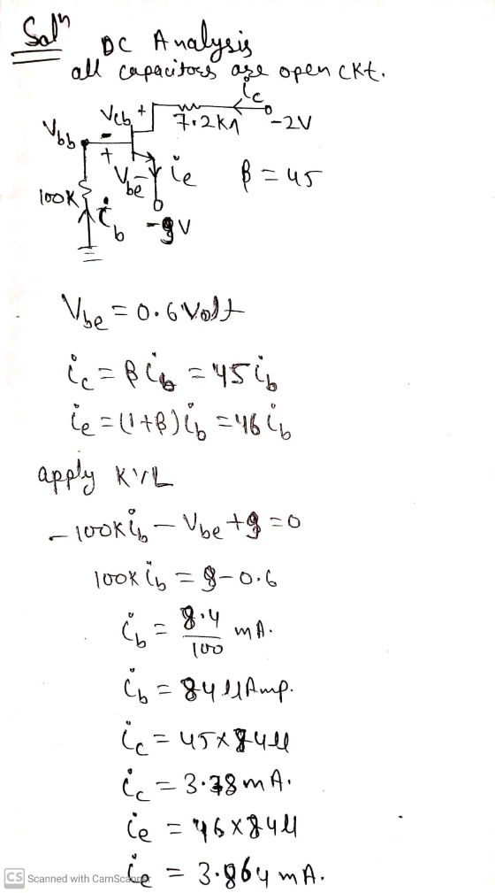
sacar ib, ic, ie, vcb, vbe, vbb,
7.2k -20 C2 Ovo C1 01 vin 0. B=45...
2) Consider the circuit below. Assume B=49 A/A, VBe=0.7V, VCEsat=0.2V. If the Collector current is Ic...
 2) Consider the circuit below. Assume B=49 A/A, VBe=0.7V, VCEsat=0.2V. If the Collector current is Ic = 9.8 mA, Find Vc, VE, VB and VBB; as well as the currents IE and IB. Hint: VBB>0. Verify your assumption. 15V V BB ic 3 Rc CS 30622 AVC RB 10k 2 B E → VE ięRE ES 33012
Vcc 10 V #2. Calculate the values of VBE, VCE, IB, Ic, and IE assuming B...
 Vcc 10 V #2. Calculate the values of VBE, VCE, IB, Ic, and IE assuming B = 150 for the Transistor Biasing Circuit in Figure 5 - 5. Simulate the circuit in Figure 5 - 5. Include the procedure and results of calculation / simulation in related section. 370k SR2 2370K BROD 2N3904 ŽR3 330 Figure 5 -5: Transistor Biasing
Problem 4 (20 %) For the circuit shown in Figure 4 determine IB, IC, and VC....
 Problem 4 (20 %) For the circuit shown in Figure 4 determine IB,
IC, and VC. Data VCC=9 V VBB=4 V R2= 165 k R1= 2.5 k Transistor
Assume VBE ≈ 0.7 V and =150
Derive all the results. Give the answers with the preestablished
prefix.
FAVOR DIBUJAR LOS CIRCUITOS
Problem 4 (206) For the circuit shown in Figure 4 determine IB, I, and Vc. Data Ve=9 V V=4V R = 165 kg R=2.5k_2 Transistor Assume VE 0.7 V and...
Problem 4 (20 %) For the circuit shown in Figure 4 determine IB,
IC, and VC. Data VCC=9 V VBB=4 V R2= 165 k R1= 2.5 k Transistor
Assume VBE ≈ 0.7 V and =150
Derive all the results. Give the answers with the preestablished
prefix.
FAVOR DIBUJAR LOS CIRCUITOS
Problem 4 (206) For the circuit shown in Figure 4 determine IB, I, and Vc. Data Ve=9 V V=4V R = 165 kg R=2.5k_2 Transistor Assume VE 0.7 V and...
Let B = {bį, b2} and C = {C1,C2} be bases for R², where b, -6--0--0--01...
 Let B = {bį, b2} and C = {C1,C2} be bases for R², where b, -6--0--0--01 1 a. Find P BEC [16 b. If [x]c = -3 de=[13] , find [x]
Problem 2. T Vcc=10v 4R3 Rc=5k12 Ko Yout C=0 Q(8=100, VBE=0.7, V=25mV, VA ) IRB IC=0...
 Problem 2. T Vcc=10v 4R3 Rc=5k12 Ko Yout C=0 Q(8=100, VBE=0.7, V=25mV, VA ) IRB IC=0 RB Fig. 3 In the common emitter amplifier shown in Fig. 3. a) Neglecting the base current (18 = 0), determine Rei and Rez to set Ice = 1 mA and the small-signal voltage gain |Apl= |Vout/Vin) = 20. [45 pt.) b) Base on the Ico given and ß = 100, choose Rp so that lg is 5% of IRB (15 pt.)
Project A B Co A $ 24,800 - 24,800 C1 +$ 9,850 C2 +$9,850 0 C3...
 Project A B Co A $ 24,800 - 24,800 C1 +$ 9,850 C2 +$9,850 0 C3 +$ 9,850 + 31,200 a. Given the following interest rates (0%, 2%, 4%, 6%, 8%, 10%, 12%, 14%, 16%, 18%, 20%), above what interest rates would you prefer project A to B? Interest rates above [ 1% b. What is the IRR of each project? (Round your answers to 2 decimal places.) IRR Project T % Project B %
Question 3. Unregulated supply Rz IL Vin IR Ib (a) The circuit on the right shows...
 Question 3. Unregulated supply Rz IL Vin IR Ib (a) The circuit on the right shows a series regulator connected to the output of an unregulated power supply. The transistor has B =50, and a 6 volt Zener diode is used. When the load current, Il, is 1 amp the de input voltage from the unregulated supply, Vin, is 11 volt, VBE = 1 volt and the Zener diode current, Iz, is 20 mA. For these conditions, calculate Iz (i)...
Assignment Score: 0% 01 45 - Hint Check Answer Question 10 of 20 > Using the...
 Assignment Score: 0% 01 45 - Hint Check Answer Question 10 of 20 > Using the data in the table, determine the rate constant of the reaction and select the appropriate units. A+2B+C+D Trial A (M) 0.340 0.340 0.680 B (M) Rate (M/s) 0.280 0.0112 0.560 0.0112 0.280 0.0448 Units
t0 = 0; tf = 20; y0 = [10;60]; a = .8; b = .01; c...
 t0 = 0; tf = 20; y0 = [10;60];
a = .8; b = .01; c = .6; d = .1;
[t,y] = ode45(@f,[t0,tf],y0,[],a,b,c,d);
u1 = y(:,1); u2 = y(:,2); % y in output has 2 columns
corresponding to u1 and u2
figure(1);
subplot(2,1,1); plot(t,u1,'b-+'); ylabel('u1'); subplot(2,1,2);
plot(t,u2,'ro-'); ylabel('u2');
figure(2) plot(u1,u2); axis square; xlabel('u_1');
ylabel('u_2'); % plot the phase plot
%----------------------------------------------------------------------
function dydt = f(t,y,a,b,c,d)
u1 = y(1); u2 = y(2);
dydt = [ a*u1-b*u1*u2 ; -c*u2+d*u1*u2 ];
end
Only...
t0 = 0; tf = 20; y0 = [10;60];
a = .8; b = .01; c = .6; d = .1;
[t,y] = ode45(@f,[t0,tf],y0,[],a,b,c,d);
u1 = y(:,1); u2 = y(:,2); % y in output has 2 columns
corresponding to u1 and u2
figure(1);
subplot(2,1,1); plot(t,u1,'b-+'); ylabel('u1'); subplot(2,1,2);
plot(t,u2,'ro-'); ylabel('u2');
figure(2) plot(u1,u2); axis square; xlabel('u_1');
ylabel('u_2'); % plot the phase plot
%----------------------------------------------------------------------
function dydt = f(t,y,a,b,c,d)
u1 = y(1); u2 = y(2);
dydt = [ a*u1-b*u1*u2 ; -c*u2+d*u1*u2 ];
end
Only...
 2) Consider the circuit below. Assume B=49 A/A, VBe=0.7V, VCEsat=0.2V. If the Collector current is Ic = 9.8 mA, Find Vc, VE, VB and VBB; as well as the currents IE and IB. Hint: VBB>0. Verify your assumption. 15V V BB ic 3 Rc CS 30622 AVC RB 10k 2 B E → VE ięRE ES 33012
 Vcc 10 V #2. Calculate the values of VBE, VCE, IB, Ic, and IE assuming B = 150 for the Transistor Biasing Circuit in Figure 5 - 5. Simulate the circuit in Figure 5 - 5. Include the procedure and results of calculation / simulation in related section. 370k SR2 2370K BROD 2N3904 ŽR3 330 Figure 5 -5: Transistor Biasing
 Problem 4 (20 %) For the circuit shown in Figure 4 determine IB,
IC, and VC. Data VCC=9 V VBB=4 V R2= 165 k R1= 2.5 k Transistor
Assume VBE ≈ 0.7 V and =150
Derive all the results. Give the answers with the preestablished
prefix.
FAVOR DIBUJAR LOS CIRCUITOS
Problem 4 (206) For the circuit shown in Figure 4 determine IB, I, and Vc. Data Ve=9 V V=4V R = 165 kg R=2.5k_2 Transistor Assume VE 0.7 V and...
Problem 4 (20 %) For the circuit shown in Figure 4 determine IB,
IC, and VC. Data VCC=9 V VBB=4 V R2= 165 k R1= 2.5 k Transistor
Assume VBE ≈ 0.7 V and =150
Derive all the results. Give the answers with the preestablished
prefix.
FAVOR DIBUJAR LOS CIRCUITOS
Problem 4 (206) For the circuit shown in Figure 4 determine IB, I, and Vc. Data Ve=9 V V=4V R = 165 kg R=2.5k_2 Transistor Assume VE 0.7 V and...
 Let B = {bį, b2} and C = {C1,C2} be bases for R², where b, -6--0--0--01 1 a. Find P BEC [16 b. If [x]c = -3 de=[13] , find [x]
 Problem 2. T Vcc=10v 4R3 Rc=5k12 Ko Yout C=0 Q(8=100, VBE=0.7, V=25mV, VA ) IRB IC=0 RB Fig. 3 In the common emitter amplifier shown in Fig. 3. a) Neglecting the base current (18 = 0), determine Rei and Rez to set Ice = 1 mA and the small-signal voltage gain |Apl= |Vout/Vin) = 20. [45 pt.) b) Base on the Ico given and ß = 100, choose Rp so that lg is 5% of IRB (15 pt.)
 Project A B Co A $ 24,800 - 24,800 C1 +$ 9,850 C2 +$9,850 0 C3 +$ 9,850 + 31,200 a. Given the following interest rates (0%, 2%, 4%, 6%, 8%, 10%, 12%, 14%, 16%, 18%, 20%), above what interest rates would you prefer project A to B? Interest rates above [ 1% b. What is the IRR of each project? (Round your answers to 2 decimal places.) IRR Project T % Project B %
 Question 3. Unregulated supply Rz IL Vin IR Ib (a) The circuit on the right shows a series regulator connected to the output of an unregulated power supply. The transistor has B =50, and a 6 volt Zener diode is used. When the load current, Il, is 1 amp the de input voltage from the unregulated supply, Vin, is 11 volt, VBE = 1 volt and the Zener diode current, Iz, is 20 mA. For these conditions, calculate Iz (i)...
 Assignment Score: 0% 01 45 - Hint Check Answer Question 10 of 20 > Using the data in the table, determine the rate constant of the reaction and select the appropriate units. A+2B+C+D Trial A (M) 0.340 0.340 0.680 B (M) Rate (M/s) 0.280 0.0112 0.560 0.0112 0.280 0.0448 Units
 t0 = 0; tf = 20; y0 = [10;60];
a = .8; b = .01; c = .6; d = .1;
[t,y] = ode45(@f,[t0,tf],y0,[],a,b,c,d);
u1 = y(:,1); u2 = y(:,2); % y in output has 2 columns
corresponding to u1 and u2
figure(1);
subplot(2,1,1); plot(t,u1,'b-+'); ylabel('u1'); subplot(2,1,2);
plot(t,u2,'ro-'); ylabel('u2');
figure(2) plot(u1,u2); axis square; xlabel('u_1');
ylabel('u_2'); % plot the phase plot
%----------------------------------------------------------------------
function dydt = f(t,y,a,b,c,d)
u1 = y(1); u2 = y(2);
dydt = [ a*u1-b*u1*u2 ; -c*u2+d*u1*u2 ];
end
Only...
t0 = 0; tf = 20; y0 = [10;60];
a = .8; b = .01; c = .6; d = .1;
[t,y] = ode45(@f,[t0,tf],y0,[],a,b,c,d);
u1 = y(:,1); u2 = y(:,2); % y in output has 2 columns
corresponding to u1 and u2
figure(1);
subplot(2,1,1); plot(t,u1,'b-+'); ylabel('u1'); subplot(2,1,2);
plot(t,u2,'ro-'); ylabel('u2');
figure(2) plot(u1,u2); axis square; xlabel('u_1');
ylabel('u_2'); % plot the phase plot
%----------------------------------------------------------------------
function dydt = f(t,y,a,b,c,d)
u1 = y(1); u2 = y(2);
dydt = [ a*u1-b*u1*u2 ; -c*u2+d*u1*u2 ];
end
Only...
Most questions answered within 3 hours.
-
Where is the error in this code sequence?
String s1 = "Hello";
String s2 = "ello";...
asked 11 months ago -
Financial data for Joel de Paris, Inc., for last year
follow:
Joel de Paris, Inc.
Balance...
asked 11 months ago -
Consider this reaction:
Al2(SO4)3 (aq)+ BaCl3
(aq) Al2Cl6 (aq)- +
3BaSO4(s) . What is the...
asked 11 months ago -
Suppose that Savneet is considering increasing her
recent random sample from 20 car rentals to 40...
asked 11 months ago -
Trucks arrive at an unloading terminal at an average rate of 120
per hour.
Trucks arrive...
asked 11 months ago -
Why are methanol and ethanol completely soluble in water while
octanol is not very little soluble....
asked 11 months ago -
A facilities manager at a university reads in a research report
that the mean amount of...
asked 11 months ago -
When the CuSO4 is rehydrated by adding water to the anhydrous
compound, is this an endothermic...
asked 11 months ago -
A ray of sunlight is passing from diamond into crown glass; the
angle of incidence is...
asked 11 months ago -
A block of mass 0.249 kg is placed on top of a light, vertical
spring of...
asked 11 months ago -
how do the kidneys compensate in the presences of acidosis
a) trigger hyperventilate
b) reserve acid...
asked 11 months ago -
Question 501 pts
The rental rate of capital to the firm increases. Which of the
following...
asked 11 months ago