
Homework Answers


Add Answer to:
(5pts) 8. For the circuits shown below, the measured voltage Vx is close to 8, 6V...
(5pts) 8. For the circuits shown below the measured voltage Vx is close to ENEE 3518...
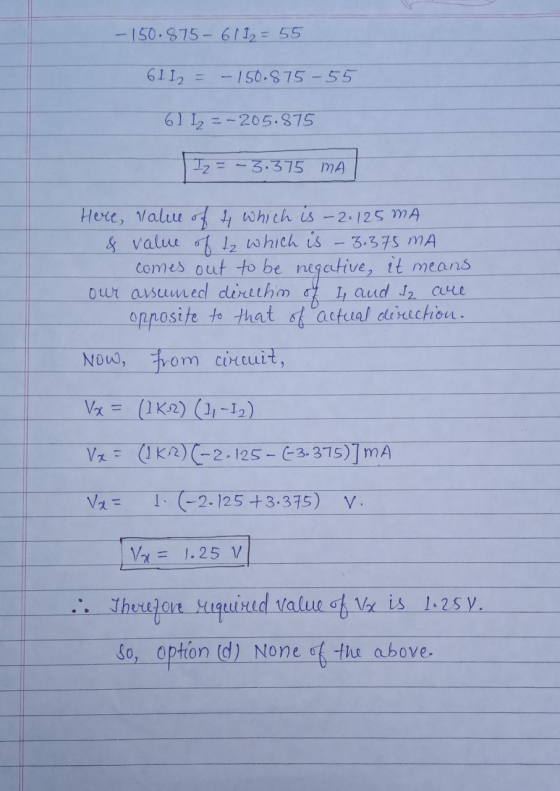
 (5pts) 8. For the circuits shown below the measured voltage Vx is close to ENEE 3518 a. 6V b. 7.5V c. 9V d. none of the above M 1kΩ 1k2 10kΩ 10kΩ M + M 5V 1kΩ 10V 오
(5pts) 9. For the circuits shown below, the maximum power transfer occurs when the resistance of...
 (5pts) 9. For the circuits shown below, the maximum power transfer occurs when the resistance of R, is close to a. Ik b. 52 c. 5.5 k2 d. none of the above 1kΩ R. RS 1kΩ 10kΩ 10kΩ R2 + R3 5V Vo Ro 10V k R, 1ΚΩ (5pts) 10. The RMS value of a sine wave with peak-to-peak value of 10V is
Final Exam, Spring 2019 ENEE 3518 (5pts) 15. A function generator with 100Hz square wave and...
 Final Exam, Spring 2019 ENEE 3518 (5pts) 15. A function generator with 100Hz square wave and zero DC offset is used as the input to the circuits shown below. Then the output wave looks like 0.01F HE с 10kΩ R + Vout in a. square wave with phase shift b. triangular wave c. sine wave with phase shift d. none of the above The following questions pertain to the circuits shown below. 3mA 1M
(6) For the circuit below, plot: (a) the transfer characteristics (b) the output, o voltage with...
 (6) For the circuit below, plot: (a) the transfer characteristics (b) the output, o voltage with 5V peak amplitude. Label the plots clearly 3 V I O (iv) Vi 8V sin( 200πt) 2ΚΩ 2ΚΩ Vi- 9V sin(200nt) -4 V -5 V (4) For each of the clipper circuits below, plot: (a) the transfer characteristics the output. 6i) 3 V 2ΚΩ 2 KS2 VQ Vi- 5V sin(200nt) DI Vi 6V sin( 200πt)
1. a,b,c,d,e,f es-hc equatC Capacitor Circuits IIpo Each of the cireuits below consists of a battery...
 1.
a,b,c,d,e,f
es-hc equatC Capacitor Circuits IIpo Each of the cireuits below consists of a battery and several capacitors. Several voltages, charges, and capacitances are indicated. Use conservation of charge and the definition of capacitance to determine the other voltages, charges, and capacitances. Hint: When necessary, replace capacitor networks with their equivalent capacitance (b) 4uC 2uF A B 4 6V SuF 8V 10v (d) 3V AI 15uC 8uC F 18uC 9V 9V E G 5V 3V C| D 10uC
1.
a,b,c,d,e,f
es-hc equatC Capacitor Circuits IIpo Each of the cireuits below consists of a battery and several capacitors. Several voltages, charges, and capacitances are indicated. Use conservation of charge and the definition of capacitance to determine the other voltages, charges, and capacitances. Hint: When necessary, replace capacitor networks with their equivalent capacitance (b) 4uC 2uF A B 4 6V SuF 8V 10v (d) 3V AI 15uC 8uC F 18uC 9V 9V E G 5V 3V C| D 10uC
The following questions pertain to the circuits shown below 5kOlms lo 30kOlms DC 10V v (5pts)...
 The following questions pertain to the circuits shown below 5kOlms lo 30kOlms DC 10V v (5pts) 3. In the ideal case, what is the voltage applied to the 30k 2 resistor? (5pts) 4. If the voltmeter reads 8.25V, what is the current lo? (5pts) 5. Without the voltmeter, what is Io? (5pts) 6. How much current is the voltmeter drawing? (5pts) 7. What is the internal resistance of the voltmeter? Page 1 of
24) For the three circuits (a), (b) and (c) shown below, the waveform of input voltage...
 24) For the three circuits (a), (b) and (c) shown below, the waveform of input voltage vy is given as shown below. For each circuit, sketch the waveform of output voltage vo for the given input voltage . Label the most positive and most negative output levels. Assume all diodes are ideal (vp- 0) and CR>> T. (10 points) +10 V-- -10 V TI ms (3 points) (b) o- (3 points) 3V (4 points) DH
(5pts) 1. You know from the lab experiments that an ideal voltmeter a. has a high...
 (5pts) 1. You know from the lab experiments that an ideal voltmeter a. has a high internal resistance at DC b. has a low internal resistance at DC c. must have an additional resistance placed in series with it so that the readings are accurate d. measures the peak-to-peak value of a sinusoid at AC (5pts) 2. If an ideal DC ammeter is connected across the terminals A and B of the circuits shown below, the meter will read amps....
Circuits The table beside circuit a below shows the current through each resistor, the voltage across...
 Circuits The table beside circuit a below shows the current through each resistor, the voltage across each resistor, and the power dissipated as heat in each resistor. Find the similar correct value for circuits b, c, and d, and put your answers in the tables shown.
 (5pts) 8. For the circuits shown below the measured voltage Vx is close to ENEE 3518 a. 6V b. 7.5V c. 9V d. none of the above M 1kΩ 1k2 10kΩ 10kΩ M + M 5V 1kΩ 10V 오
 (5pts) 9. For the circuits shown below, the maximum power transfer occurs when the resistance of R, is close to a. Ik b. 52 c. 5.5 k2 d. none of the above 1kΩ R. RS 1kΩ 10kΩ 10kΩ R2 + R3 5V Vo Ro 10V k R, 1ΚΩ (5pts) 10. The RMS value of a sine wave with peak-to-peak value of 10V is
 Final Exam, Spring 2019 ENEE 3518 (5pts) 15. A function generator with 100Hz square wave and zero DC offset is used as the input to the circuits shown below. Then the output wave looks like 0.01F HE с 10kΩ R + Vout in a. square wave with phase shift b. triangular wave c. sine wave with phase shift d. none of the above The following questions pertain to the circuits shown below. 3mA 1M
 (6) For the circuit below, plot: (a) the transfer characteristics (b) the output, o voltage with 5V peak amplitude. Label the plots clearly 3 V I O (iv) Vi 8V sin( 200πt) 2ΚΩ 2ΚΩ Vi- 9V sin(200nt) -4 V -5 V (4) For each of the clipper circuits below, plot: (a) the transfer characteristics the output. 6i) 3 V 2ΚΩ 2 KS2 VQ Vi- 5V sin(200nt) DI Vi 6V sin( 200πt)
 1.
a,b,c,d,e,f
es-hc equatC Capacitor Circuits IIpo Each of the cireuits below consists of a battery and several capacitors. Several voltages, charges, and capacitances are indicated. Use conservation of charge and the definition of capacitance to determine the other voltages, charges, and capacitances. Hint: When necessary, replace capacitor networks with their equivalent capacitance (b) 4uC 2uF A B 4 6V SuF 8V 10v (d) 3V AI 15uC 8uC F 18uC 9V 9V E G 5V 3V C| D 10uC
1.
a,b,c,d,e,f
es-hc equatC Capacitor Circuits IIpo Each of the cireuits below consists of a battery and several capacitors. Several voltages, charges, and capacitances are indicated. Use conservation of charge and the definition of capacitance to determine the other voltages, charges, and capacitances. Hint: When necessary, replace capacitor networks with their equivalent capacitance (b) 4uC 2uF A B 4 6V SuF 8V 10v (d) 3V AI 15uC 8uC F 18uC 9V 9V E G 5V 3V C| D 10uC
 The following questions pertain to the circuits shown below 5kOlms lo 30kOlms DC 10V v (5pts) 3. In the ideal case, what is the voltage applied to the 30k 2 resistor? (5pts) 4. If the voltmeter reads 8.25V, what is the current lo? (5pts) 5. Without the voltmeter, what is Io? (5pts) 6. How much current is the voltmeter drawing? (5pts) 7. What is the internal resistance of the voltmeter? Page 1 of
 24) For the three circuits (a), (b) and (c) shown below, the waveform of input voltage vy is given as shown below. For each circuit, sketch the waveform of output voltage vo for the given input voltage . Label the most positive and most negative output levels. Assume all diodes are ideal (vp- 0) and CR>> T. (10 points) +10 V-- -10 V TI ms (3 points) (b) o- (3 points) 3V (4 points) DH
 (5pts) 1. You know from the lab experiments that an ideal voltmeter a. has a high internal resistance at DC b. has a low internal resistance at DC c. must have an additional resistance placed in series with it so that the readings are accurate d. measures the peak-to-peak value of a sinusoid at AC (5pts) 2. If an ideal DC ammeter is connected across the terminals A and B of the circuits shown below, the meter will read amps....
 (5pts) 1. You know from the lab experiments that an ideal voltmeter a. has a high internal resistance at DC b. has a low internal resistance at DC c. must have an additional resistance placed in series with it so that the readings are accurate d. measures the peak-to-peak value of a sinusoid at AC (5pts) 2. If an ideal DC ammeter is connected across the terminals A and B of the circuits shown below, the meter will read amps....
 Circuits The table beside circuit a below shows the current through each resistor, the voltage across each resistor, and the power dissipated as heat in each resistor. Find the similar correct value for circuits b, c, and d, and put your answers in the tables shown.
Most questions answered within 3 hours.
-
Where is the error in this code sequence?
String s1 = "Hello";
String s2 = "ello";...
asked 10 months ago -
Financial data for Joel de Paris, Inc., for last year
follow:
Joel de Paris, Inc.
Balance...
asked 10 months ago -
Consider this reaction:
Al2(SO4)3 (aq)+ BaCl3
(aq) Al2Cl6 (aq)- +
3BaSO4(s) . What is the...
asked 10 months ago -
Suppose that Savneet is considering increasing her
recent random sample from 20 car rentals to 40...
asked 10 months ago -
Trucks arrive at an unloading terminal at an average rate of 120
per hour.
Trucks arrive...
asked 10 months ago -
Why are methanol and ethanol completely soluble in water while
octanol is not very little soluble....
asked 10 months ago -
A facilities manager at a university reads in a research report
that the mean amount of...
asked 10 months ago -
When the CuSO4 is rehydrated by adding water to the anhydrous
compound, is this an endothermic...
asked 10 months ago -
A ray of sunlight is passing from diamond into crown glass; the
angle of incidence is...
asked 10 months ago -
A block of mass 0.249 kg is placed on top of a light, vertical
spring of...
asked 10 months ago -
how do the kidneys compensate in the presences of acidosis
a) trigger hyperventilate
b) reserve acid...
asked 10 months ago -
Question 501 pts
The rental rate of capital to the firm increases. Which of the
following...
asked 10 months ago